At the beginning of the 2005 Ford GT program, I made a decision that turned out to be the biggest mistake of my career. It led to a recall of all cars produced up to that time, a stop-build order, a stop-sales order, and a stop-drive order. In fact, a man who bought one of the first production cars for a very large sum of money was at a track day, and we had to call him to tell him to stop driving the car immediately. Talk about embarrassing!
What we had discovered was that some of our new suspension arms were splitting around the bushings. In the image above you can see what happened. The picture shows a cracked arm with the bushing already removed. This meant that the bushings were no longer properly held in place and the suspension arms could separate from the rest of the vehicle, potentially leading to very bad things, to put it mildly.
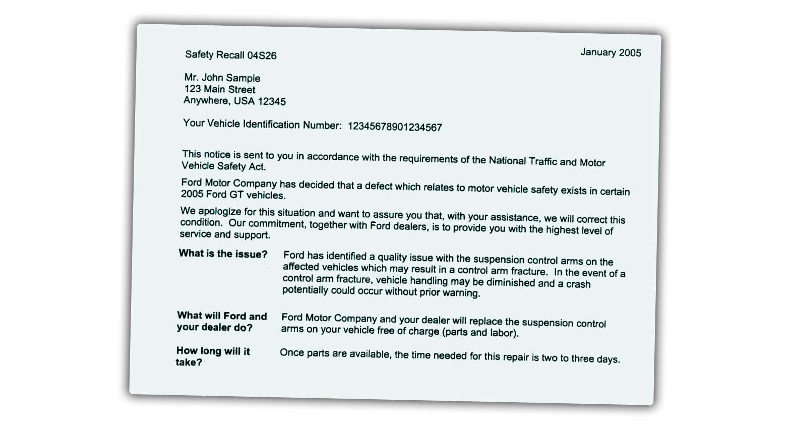
The National Highway Traffic Safety Administration’s official recall notice to customers(shown above) — which covers “283 Ford 2005 GT passenger vehicles manufactured from February 20 through December 9, 2004” — reads: “Ford has identified a quality issue with the suspension control arms on the affected vehicles which may result in a control arm fracture. In the event of a control arm fracture, vehicle handling may be diminished and a crash potentially could occur without prior warning.”
How Could This Happen?
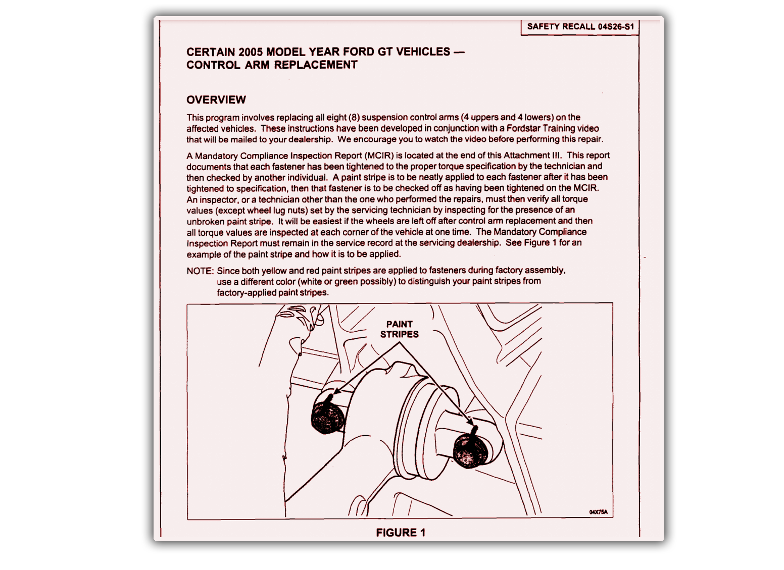
So, how did this happen? What could I have possibly done that would result in such an embarrassing situation? Let’s turn the wayback machine all the way to early 2002. The Ford GT engineering and design program had just started, and we were discussing how to set this car apart from every other supercar out there. Since this was meant to be the flagship of the company and the centerpiece of the 100th birthday celebration scheduled for the summer of 2003, we needed something truly special that would not only look the part but at the same time make an engineering statement.
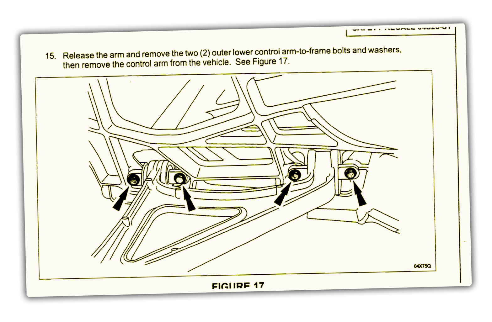
Often, when a company builds a limited production flagship, the goal is to create a testbed for new technologies that then filter down to more mainstream products. That’s what we had in mind when developing the GT, so as I was leading the team that designed the suspension, steering, brakes, and spaceframe, I wanted to do what I could to be as innovative as possible. The result was many discussions with potential suppliers to see what they were developing, what new technologies they were working on, and how these could benefit our car. I wanted to do something fun and exciting with the suspension.
Throughout the automotive industry, there are basically three different materials from which suspension components are made: cast iron, steel, and aluminum. Cast iron components are made using a casting process; steel components can be either forged, cast, or stamped; and aluminum components are usually cast or forged. Aluminum can also be stamped but this is not common practice in suspension components since the thickness of material required to achieve the strength needed for suspension parts would lead to too much tearing in the stamping process.
These days, carbon fiber is making an appearance in suspension parts, especially in race cars, but in 2002, that technology was still far from being viable even for a limited production car. Since the Ford GT was to be an expensive, high-end car, and since we wanted the car to have exceptional handling performance, we needed the suspension components to be as light as possible. This meant that aluminum was our only real choice. The next decision then was cast vs forged.
We Had a Decision To Make
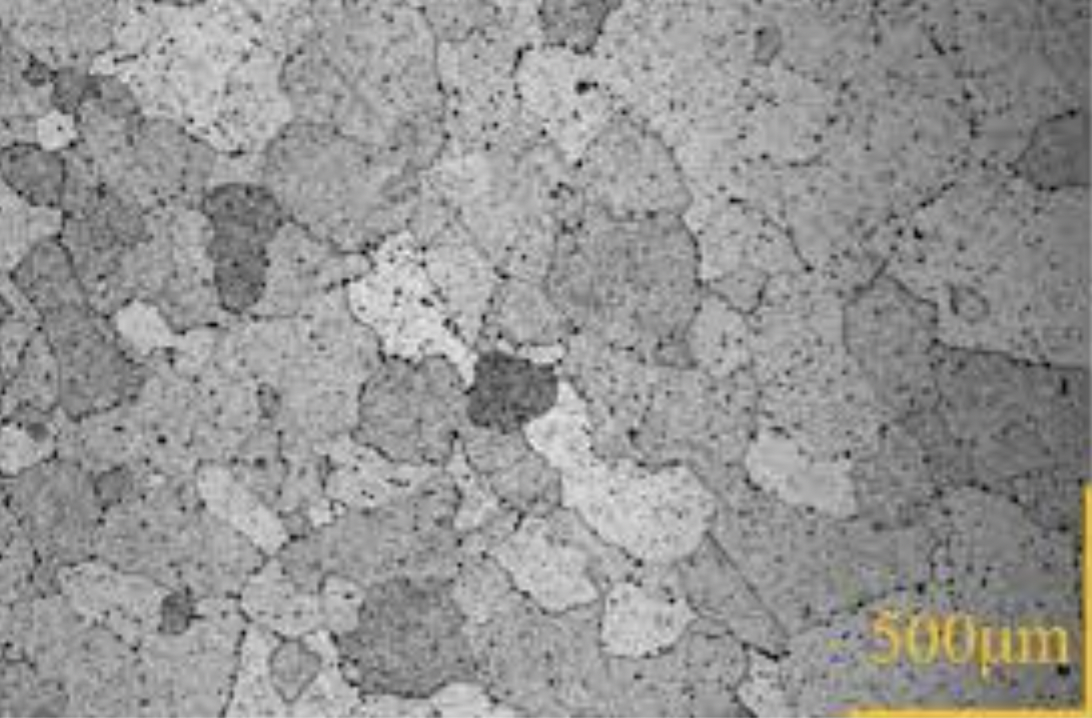
In order to understand how the choice of cast vs. forged is made, we need some background on the differences between the two processes and how they affect aluminum. If you were to cut open a piece of aluminum and look at it under a high power microscope you would see something similar to the image above.
What you are seeing is the “grain” of the material and in this example it is fairly randomly oriented and is what you would expect to see in a cast part. In a forged part, this same grain exists but it will be elongated and aligned with the part. As an example, here is an image of an axle hub (taken by HHI Forgings); the hub has been cut to show the grain direction created by the forging process:
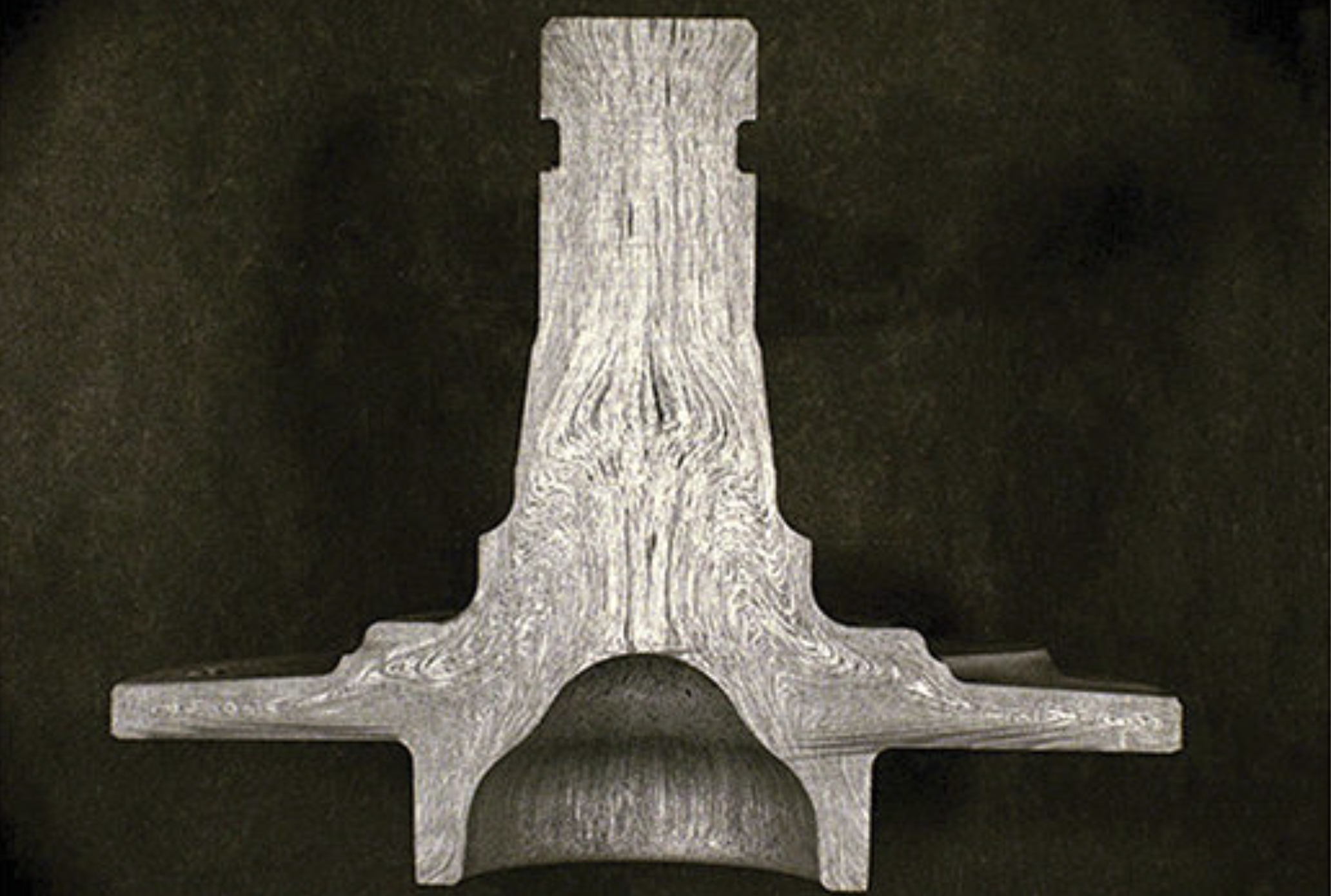
This example shows a steel part, but the effect would be the same in aluminum and clearly shows how the grain has been oriented along the length of the part. The result is a part that has much higher fatigue strength and durability. For this reason, forging is the natural choice for parts that need high strength and high durability. Unfortunately, forging is expensive and uses expensive tools. There are also limits on the final shapes that the forging process can produce and these need to be taken into account by the suspension engineer as the part is designed.
Casting, on the other hand, solves a number of these limitations while introducing some others. Whereas forging involves essentially hammering metal into shape, in a casting, molten metal is poured, or pushed, into a mold. The metal is allowed to cool for a short period of time, the mold is then opened and the finished part is removed. This process allows for a part that is much closer to what the designer really wants, with all the bosses and protrusions that may be necessary. It also only requires a single die.
The downside is that melting aluminum creates the random grain shown in the image before the last one and as a result, the strength and durability of the part is not as high as a forging. That’s not to say that casting is a bad choice. On the contrary, cast aluminum is often the best choice especially for parts that have very complex shapes. Strength and durability compromises are simply limitations that the suspension designer must take into consideration when designing the parts.
So where did that leave the 2005 Ford GT suspension team? We knew we wanted the best for our car, and since this would be an expensive car, we could afford more expensive parts. Forged aluminum seemed a natural choice.
Semi-Solid Casting
As we were discussing our material and manufacturing choices with potential suppliers in early 2002, one of those suppliers introduced us to a new aluminum casting technology which used a process called semi-solid casting. Basically, semi-solid casting is a hybrid between casting and forging and attempts to achieve the best of both worlds: the strength and durability of a forging with the complex shapes possible with casting. The way this was achieved was to heat a block of aluminum to a temperature just slightly below its melting point and inject that at very high pressure into a mold. When aluminum is heated to just below its melting temperature, it has the consistency of butter and you can literally slice it with a knife. I had the opportunity to do this, and it feels really weird, partially because unlike steel, when you heat aluminum, it doesn’t change color. This is one of the reasons it is so hard to weld aluminum. You can’t see what is happening to the metal until it suddenly falls into a puddle at your feet.
So, imagine a log of aluminum the size of a loaf of bread sitting on a table and being able to slice it with a knife. That is what it was like. Pretty cool.
This heated log of aluminum is then placed into a ram that pushes it into a mold at an extremely high pressure. The result of this is that the grain structure that existed in the original log is preserved since the aluminum was never melted. In fact, the process of forcing the metal into the mold helped to create an elongated grain structure similar to forging. And since it was a casting process, complex shapes could be achieved. The best of both worlds! Or so we thought.
And we were right for a long time. All through the multiyear development process of a new car, the parts that our supplier provided us were stunning. They were gorgeous and we did not have a single failure in any of our testing. And we beat the crap out of these parts. Even though we knew these vehicles were going to be cherished and babied by their owners, we wanted the suspension to last as long as — and be as durable as — any other suspension the company produced. We ran all the usual strength tests that every other Ford product had to withstand, and the car passed with flying colors.
There is a test where the car is driven through a large, deep pothole at high speed with the brakes locked. Running this test feels like the car is going to explode on impact — it is so devastatingly destructive. The Ford GT ran through it and didn’t flinch. In fact, the suspension alignment barely changed. We had never seen a car perform this well in this test.
Everything pointed to a real success story, and the suspension team — and our supplier — were beyond pleased with the results.
Our Process Wasn’t “Capable”
Unfortunately, a massive storm was brewing on the horizon. What we didn’t know was that our new process was not “capable.” In manufacturing, engineers talk about something called “capability,” which refers to the ability of a process, a method, a tool, and every production step, to produce the same part over and over and over again. A “capable” process will be able to produce good parts 99.999% of the time. The other 0.001% of parts will have some flaw which is intended to be caught by the quality controls that every factory has in place. This means no bad parts ever make it to the customer because few bad parts are made in the first place and those that are bad are caught before being shipped out the door. Of course, things don’t always turn out so perfectly and our new process was a perfect example. What we discovered after weeks of investigation was that our supplier was only producing good parts about 5% of the time. It was a disaster!
The discovery came after we had been in production for a while and had already produced over 400 vehicles. One day we received a call from a dealership in Arizona that was performing a pre-delivery inspection of a vehicle. One of the technicians was looking under the car and noticed something very odd about one of the suspension arms. He contacted the team and sent us photos of what he saw. Needless to say, my heart sank into my stomach. The photos showed a large fracture in the aluminum holding one of the bushings in the arm. Had this vehicle been driven and encountered something like a pothole it could easily have led to a complete failure of the arm. For a suspension engineer that is the stuff of nightmares!
We got all our managers and chief engineers together, talked with our legal team and immediately issued a recall notice. Because of the potential severity of the failure, we then also stopped building cars, stopped delivery of cars, and contacted each customer individually to request they not drive their cars until we had a solution identified and implemented. That was when we learned that one of our most prominent customers was enjoying his car at a track day. It took a little while, but we were able to contact him at the track and requested he park the car for the rest of the day. Worried he would consider this a gross imposition, we fully expected some very negative feedback, but he was more than gracious and understood that high performance vehicles can break and he immediately parked the car.
Now that we had identified the problem, we needed to determine how many other bad parts were out there and how this problem had gone undetected for so long. After much investigation, in which our team effectively took over the supplier’s factory and worked for many weeks to understand the problem and then try to fix it, we concluded that the problem was something called a “cold shut.”
The Cold Shut

To understand what a “cold shut” is, we need to look at the details of what happens when aluminum is cast, and at some of the characteristics of the aluminum material itself. Aluminum is a very reactive material. When you look at a piece of aluminum, you are actually not looking at aluminum itself but rather a very thin, tough oxide film. Pure aluminum instantly reacts with oxygen in air and forms this thin layer. Once this ultra-thin layer of oxide is formed, it acts as a protective barrier for the pure aluminum underneath, and no further reaction takes place. When aluminum is melted in a furnace in preparation for casting, this oxidation will happen as well. The factory prevents this by flooding the molten metal with an inert gas. This is fine while the metal is still in the cauldron but once it gets poured out into a mold, it is exposed to air and the oxidation starts to happen again.
The next part of understanding our problem is to know a bit about how some suspension casting molds are made. Every mold has a main opening where the molten metal is poured in. This is called the sprue, and once the part solidifies and is removed from the mold, it becomes a large block of metal that is cut off and recycled. The reason the sprue is large is because it needs to stay hot and molten longer than any other part of the mold. Molten metal flows from the sprue through the rest of the mold until it is completely filled, and the cooling and hardening process can begin.
The other aspect of mold design that is critical here is that it is important that the cooling process start first at the part extremities that are farthest away from the sprue and slowly progress towards the sprue. The reason for this is that aluminum shrinks slightly as it cools. If the cooling process starts farthest away from the sprue, then the molten metal in the sprue can continue to feed the mold with more metal as the cooling metal shrinks. If a section of metal part way down the mold cools too soon then the metal farther away that has not fully cooled cannot continue to be fed by the sprue as it cools and shrinks. This will result in the creation of voids called “shrink porosity.”
This porosity is not visible on the outside but makes the part look a little like Swiss cheese on the inside. The potential result is greatly reduced strength in that area if the porosity is not well controlled. While most porosity is not visible from the outside, it can be seen under a special X-ray machine. For this reason, many castings are 100% X-ray checked as part of the quality control process to make sure any porosity does not exceed a predetermined size and amount and is not located in areas that would compromise the strength of the part. You don’t really want the inside of your part to resemble Swiss cheese. That would be bad.
OK, back to our part. In many suspension arms, ours included, the sprue is often near what will later become the outer ball joint. This means the areas that hold the bushings are usually furthest away from the sprue and are the last to be filled with metal. To help promote proper cooling and solidification, and to reduce the amount of metal that needs to be injected into the mold, inserts are placed in the mold where the bushings will later go. The image above points out how the inserts have left voids where the bushings will go.

These inserts look very similar, but are slightly smaller than the bushings themselves, and they force the molten metal to split direction, with half the metal flowing over the insert and the other half flowing under the insert.
The two halves of the flow then join together again on the other side of the insert. Unfortunately, as the metal is flowing through the mold, it is exposed to air and the oxidation process we talked about earlier is taking place. At the same time, the metal is starting to cool. This means that when the two halves of the metal flow meet each other on the other side of the insert (as shown in the animation above), it is actually two oxidized and partially cooled surfaces that are meeting. This is bad for making sure that the metal fully blends and mixes together.
The solution is to provide what is called an overflow which is a small chamber in the mold that this oxidized and poorly mixed metal can flow into and which would then later be cut off after the part is finished. It works great in theory, especially for a casting process that uses molten metal. However, in our process, it didn’t work so well. After the metal flow split around the insert, it did not fully mix and “knit” back together, and created the aforementioned “cold shut”. The metal was already too cold to mix properly and while it looked like everything was OK, the part had much less strength in that area and could easily split when the bushing was later pressed into the arm.
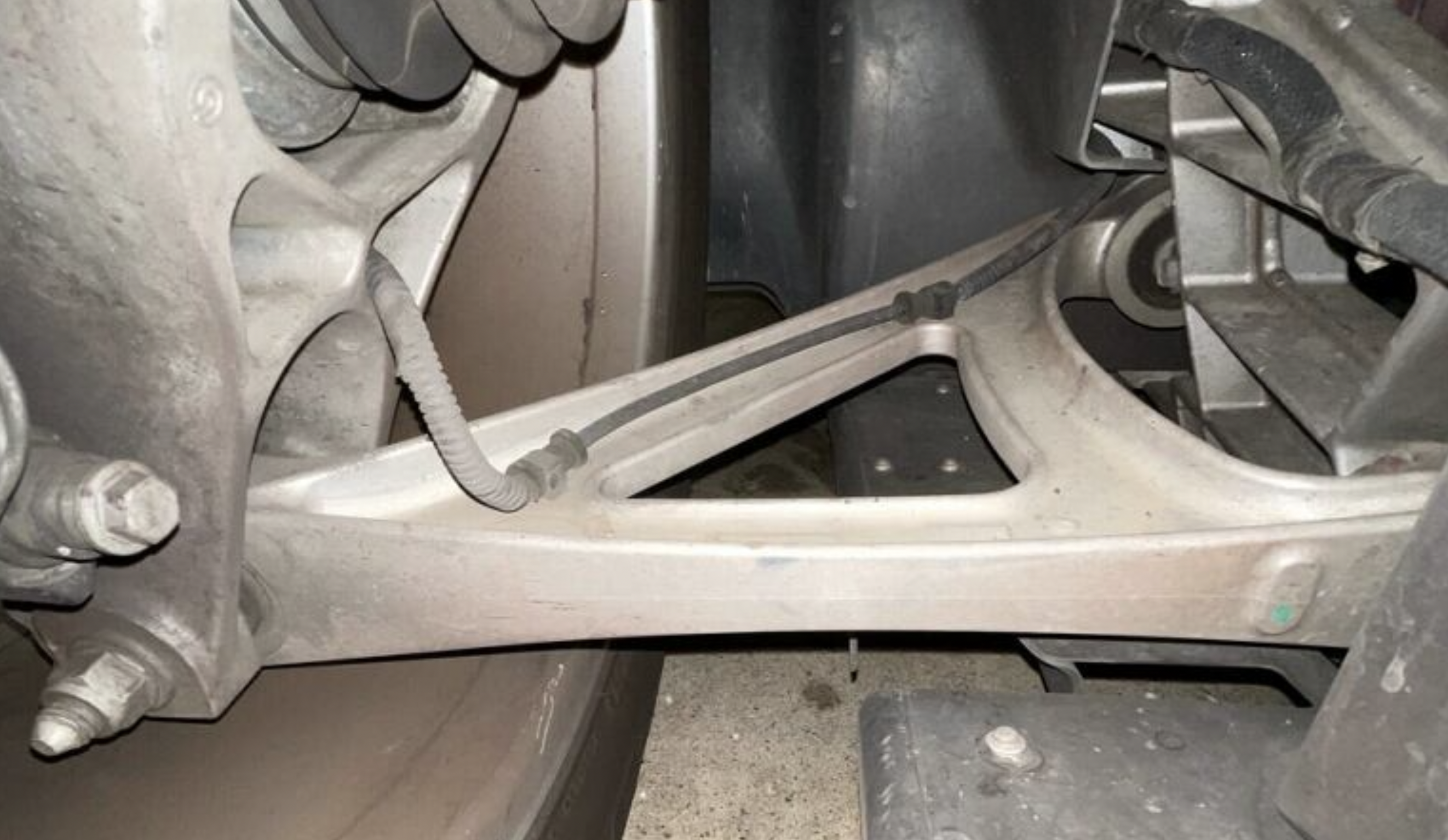
So, you might ask, why didn’t the X-ray process find this problem in the same way it finds porosity? The answer is that unfortunately, a cold shut is not the same as porosity. With a cold shut there is not actually a void in the metal, and since X-rays pick up differences in material density (like the difference between the density of your skin and your bones, or the difference between the metal of the arm and the gasses of the porosity), a cold shut does not include such a change in density. As far as the X-ray was concerned, everything looked perfect. We had to find a different detection method and that turned out to be ultrasound. While a cold shut does not leave a void, it does leave a surface inside the metal and ultrasound waves will bounce off this surface and be detected. We used ultrasound on all the suspension arms we had produced up until then and it showed a majority of them had the same problem. It would have been only a matter of time before more arms failed in customer cars.
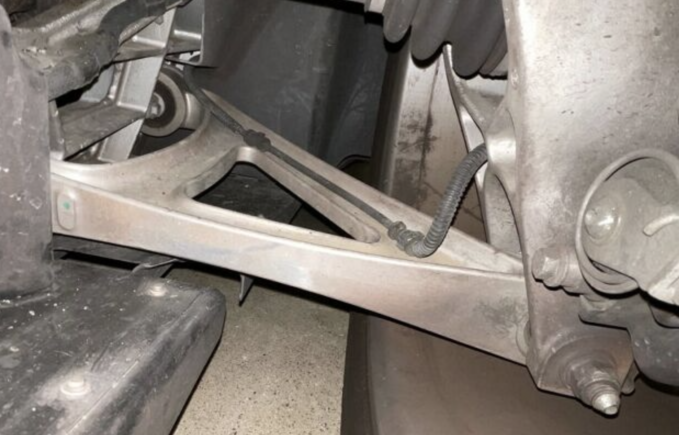
In the meantime, we were continuing to work with our supplier to improve the casting process, but after many fruitless weeks we concluded that we needed to abandon the semi-solid casting process and quickly redesign the control arms to be made as forgings. We had actually started the redesign process many weeks earlier as a back-up in case the new process could not be made to work, and now that the fateful day had arrived, it turned out to be time well spent.
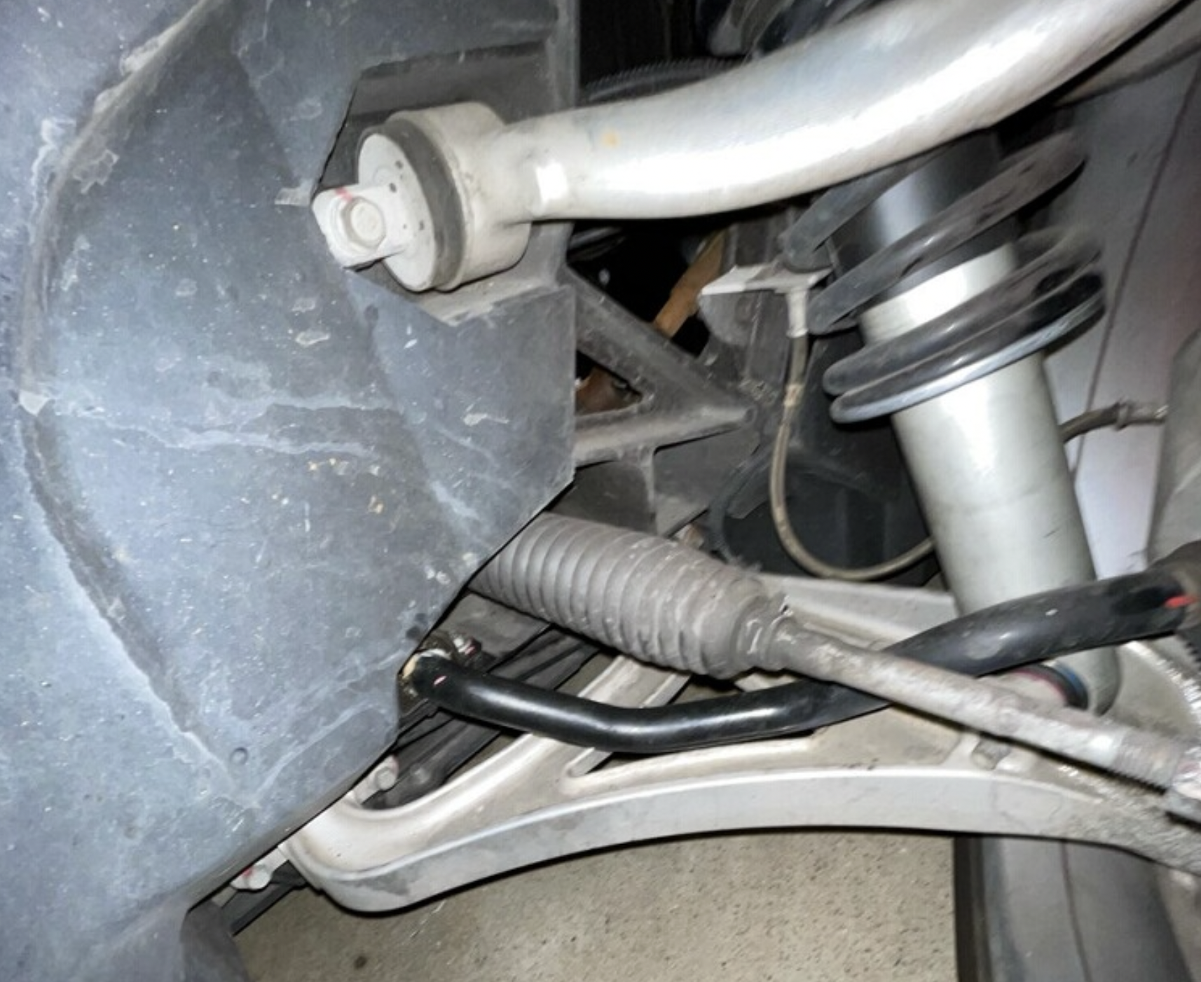
We switched to a new supplier, and they very quickly started developing and making forging tools. Still, making forging tools is a 5-6 month process and we did not want to be out of production that long. We had to find an interim solution that would allow it to restart production as soon as possible. That solution was to take our new forged designs and machine arms from solid billets (see image below from Ford GT Forum). This turned out to be an undertaking no one had ever attempted before.
There were eight arms in each vehicle. We had already built over 400 cars ,and we needed to support production of nine vehicles per day for approximately 6 months. That meant we needed to billet-machine almost 13,000 arms. This of course required 13,000 pieces of 6061-T6 billet aluminum. No aluminum supplier had that much billet on hand nor could they supply it in the time we needed. We were stuck.
An International Hunt For Billet Aluminum
Somehow we needed to buy a huge amount of billet aluminum so we could continue production. We ended up putting together a team of engineers and procurement experts who spent day after day calling anyone and everyone throughout the world who might have material on hand and ask if they would sell it to us. Australia, China, Russia, Europe. We called everybody, and did manage to buy enough material to restart production a few weeks later and continue until the forged parts were tooled, produced, and fully tested. Everyone breathed a huge sigh of relief when the finished forged parts finally arrived and the assembly plant could be switched over from the billet parts.
To this day, there are hundreds of 2004 (2005 model-year) Ford GTs out there with billet machined arms. So, if you ever see a 2005 Ford GT, ask the owner to open the rear clamshell and have a good look at the suspension. You can easily see the rear upper arms and it is very obvious if it is a forged or a billet part. The billet parts have those distinctive lines that look like a topographical map while the forged parts are completely smooth. And if you see the billet machining marks, you can now tell the owner the whole story of why they are there.


This is a fantastic article! I’m an engineer of a different flavor, and it’s… it’s… just heaven listening to a serious automotive engineer explain the real details of how cars are designed and built. Give us an article like this every day! (JK; just one per day would never be enough.)
This is a beautifully written and highly informative article. Just wow. I never thought I’d learn this kind of insider info and the storytelling of a complex technical issue made it easy to be fascinated. THANK YOU!
Can we just recognize for one moment the quality of that casting animation?? I loved that! Nice work Autopian staff
Agreed, it’s simple and clear. Great work!
Credit goes to Jason Torchinsky. Man is a genius.
Aren’t mistakes the best part of developing vehicles? Sometimes I miss working in the automotive industry.
Great article! Now let’s get an explanation from the Pinto fuel system engineer.
This was a great article. I learned a lot about the engineering side of my work. I’m part of the crew building the current Ford GT, so I can heavily relate to this article.
The metallurgy descriptions make sense when I think about the components in the cars I build. I can see the cast rear structures, billet cnc’d strut mounts, even the funny patterning of the grain of the control arms. Didn’t know why it looked like that till now.
P&W fan frame, huh?
Great article! Brought back scary memories of a similar situation with injection molded 6-6 Supertough Nylon for attaching hardware on concrete forms. These things spend their lives being beaten with hammers by guys in a hurry. Split like you hit ’em with an ax on the far side of the main longitudinal diameter. The samples could not be killed, and I tried. The gates and vents got moved on the production parts. They got dumped back in the melt hopper after restructuring gates and vents. Came out good after that!
Keep it up, I love the inside baseball articles.
It’s like I say at work—if I can’t use it as a hammer in a pinch, it’s not built well enough. On a construction site, everything is a hammer. Design accordingly.
You guys are truly knocking it out of the park with the start here.
As as guy who lusts after the GT, having seen and touched one in a local pro golfer’s garage at 12 or 13 y/o, this was simply amazing. Gonna keep working my ass off so I can come back to ask whether I should look for the billet or forged arms.
Not to say the other articles aren’t, but this article is fantastic, love the technicals. STAB article almost killed me by laughter. Poor David and even sadder nice lady was entertaining as well.
This was the in depth, concise, and real explanation of things I had no idea about yet very much wanted to know.
Thanks!
Fascinating in-depth inside information…thanks!
Fantastic article! As en engineer something like this is definitely a nightmare scenario but you seemed to handle it very well!
A follow up question though, would the billet parts end up being any stronger/more hardy than the new forged parts and therefore more desirable?
Joining in with the other comments that this was a great article. Looking forward to more like this!
Do you know what’s the solution to this problem now, 20 years later?
I guess today they’d look at making it out of carbon fibre, although I assume that comes with it’s own new and exciting production problems to overcome.
>Throughout the automotive industry, there are basically three different materials from which suspension components are made: cast iron, steel, and aluminum.
How times have changed! I’m in aerospace composites engineering but we’re branching out into automotive and are currently making prototype control arms out of compression molded chopped fiber PEKK/CF composite.
This is a fucking excellent article. It’s exactly what Jalopnik is missing. I’m not even really all that interested in all this engineering and sciencey stuff, but the right story and even more importantly, the right author, can make reading all of that engineering mumbo-jumbo fascinating. Keep it up!
Awesome article. That kind of problem was a nightmare of mine. That’s why I feel so much better building one-off machines now. Mistakes happen but the logistics behind them are not that complicated.
I was wondering if they had tried re-gating the original mold to fill at both of the bushings and then bled off at the ball joint?
I think that could have worked, but I do agree that a forged arm is better.
A big thank you from this decidedly non-engineer as the way you wrote allowed me to understand (and very much enjoy) the article- usually I am interested but don’t understand and end up moving on. Sincere kudos to The Autopian! As many have stated, this is so much better than the old J site. I’m stoked!
I second this. I am not an engineer either, but the way this was so well written worked for me!
My job one summer (at what was then the University of Missouri-Rolla) was in the metallurgical department. One of the profs was working on different coatings for lost-foam castings. I’d help prepare the forms and also help pour the molten aluminum alloy, but my main job was, after the casting was complete and cooled, to take a sledgehammer to the casting and break it up into as many small pieces as possible, and then make note of where there were any voids or other imperfections in the casting.
That was a ridiculous job, but it was fun playing with the hot wire, making interesting foam creations.
Why pay for a fancy X-ray machine when you can get the same results with nothing more than a sledgehammer and a couple of undergrads?
Hey the article that gets me to login in, thanks for posting this!
I work with plastics but the concepts are generally the same, and hearing about this in an accessible format rather than an FMEA/CAPA teardown is cool as hell. Scary to think that you didn’t see the failure in testing, but then it shows up out in the field. That’s the stuff that keeps engineers awake at night, but also keeps us employed. That and, “Wait, what shift is running that trial!?”
Not expecting an answer, but something that springs to mind is once the production got going, the amount of recycled content in the feedstock probably went up, as you’re reusing sprues and failed parts. Aluminum is pretty forgiving in that regard I imagine, but did the extra heat cycles eventually cause more oxidation fronts and make this issue worse than when you were at small scale? Something I’ve had to keep in mind in my own work, reviewing the process when you’re running for 24hrs vs a 2hr trial can be eye opening.
This was a great journey to read! I’ve been really curious about the adoption of composite/bonding in manufacturing and thought, well it gonna be something invisible fails! This is much along those lines.
I do want to add the following. I understand your humble tone is part of the style of this article, but people who honestly own a mistake and address them are absolutely critical in our complex world. There is nothing at all to be embarrassed about.
Also, somebody should at least buy that tech in Arizona a beer. Every person in the process can turn out to be a critical contributor and in this case, possibly save a life.
This is the nerding out to science I never knew I needed.
Anyone else wondering who the high profile customer was? Clarkson?
I’m pretty sure the customer they contacted was John Shirley, the retired Microsoft exec. He was the gentleman who paid $557,000 at a charity auction fo the first customer Ford GT, chassis #10 (1-9 we’re saved for internal use with Ford executives). Clarkson didn’t get his car until later when Ford built the batch that going overseas. I say this as I sold Fords from 1997-2020 and we got in chassis #193 for 2005 and it had the bullet aluminum control arms installed at SSV then sent to us. The control arms are STUNNING as they shine once cleaned up.
So, as someone with no engineering experience and basically absorbing this info for the first time, I still feel a bit confused…At the end of the day, which is more desirable to have, the forged or the billeted parts?
That was (one of) my question(s) as well.
Awesome article!
I’m also confused – good to see I’m not the only one! I’ll add my questions to your comment; maybe someone can answer them as well.
– I’m still working on what a billet is – is a billet just a fancy way to describe a raw block of aluminum?
– How are billeted parts made? Does this just involve taking a block of aluminum and chiseling away bits to make the part?
– How are the billets made? Are the billets forged? If so, would a part made from a billet of forged aluminum have the same strength as a forged part?
It is definitely an interesting article, although I think I might be too dumb to understand some of the finer points. Engineering is tough.
Yup, big ‘ol hunk of aluminum, usually 6061-T6, but could be a range of other heat treat/metallurgic combos.
Yup, as with art, take big ‘ol hunk and carve off anything that isn’t a control arm. Usually with a CNC mill. They’re fun!
It depends, some are cast, most are pressure-formed into a long stick, then bandsawed to the appropriate length, sometimes the billet is given the smush-ola (forged) in a variety of ways before being milled. Forged billet is strongest for the reasons listed above. Think of a loose snowball versus the one you hand packed for 5 minutes while you looked for your little brother. The smushed one is a forging. Look up forged billet wheels and gasp at the expense. Hope it helps.
1 -yes, 2 -yes
3 -I dont know! I’ve wondered the same thing for many years
I’m not a materials or manufacturing engineer, but I think I can help… It seems there are several meanings for “billet”, depending on the engineering context, but I think here we’re talking about aluminum that is processed into a bar or thick plate by a type of forging process. You get forged material properties, with those nice stretched out grains, but they’re aligned to the shape of the more or less rectangular billet, rather than a specific forged shape. Better than cast, not quite as good as a well designed forging.
There will be two major down sides though to a part machined from billet: you can’t get every feature of forging because of the limitations of CNC machining; and you start with lots of extra material and spend a heck of a lot of time removing aluminum which then has to be recycled. Notice in the picture of the forged part that the shape is a lot chunkier and especially that the long inner rib on the right side has a gap where it doesn’t attach to the rib across the bottom. You end up with a strong part, but it’s probably heavier than the forged part. Also, it’s way more expensive to produce, so Ford probably lost a chunk of it’s profit margin in order to keep it’s customers safe and happy.
Long story short, don’t replace your forged suspension links with machined billet ones to increase the performance of your GT40.