
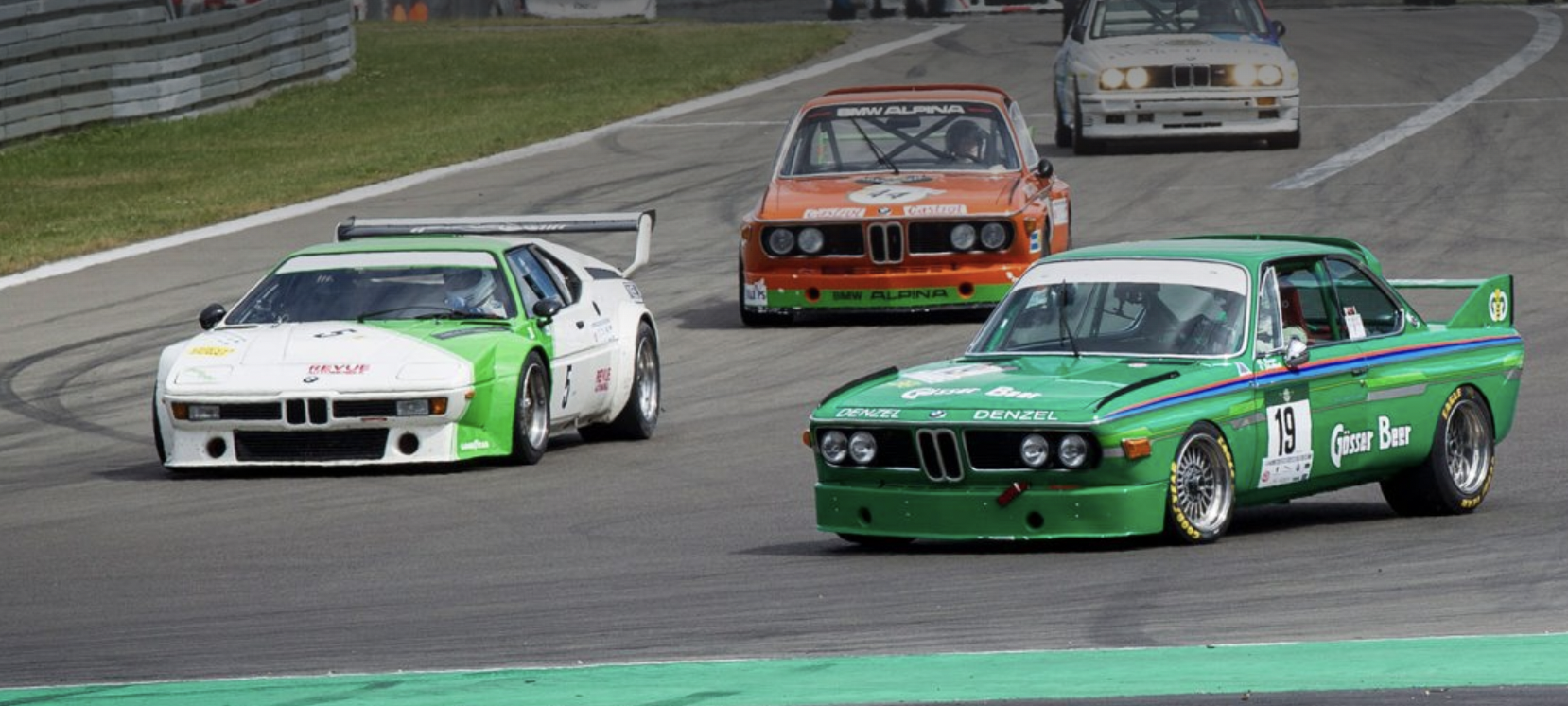
My fellow Autopians. Welcome back to another edition of Ask an Engineer. This time we are going to answer a question that multiple people have sent in. Many of you may have noticed that some race cars seem to have a lot of negative camber on their front wheels (i.e. the tire appears to be leaning in wards at the top). Much more so than on the rear wheels. It’s almost as if they are going for a “stanced” look.
Of course, a true “stanced” look is much more severe than what we see in race cars, but you get the idea. Lot’s of negative camber — way more than you would see from the factory in a normal street car. Why is this? What do race car builders know that the rest of us don’t?
There are many reasons why a race might want a lot of camber on the front. During cornering, the tire rolls under, and high camber will help keep more of the tread in contact with the road under those high sideloads.
Also, Macpherson strut suspensions (see example below) don’t have very good camber control due to flexibility of the strut rod and a digressive camber curve (we’ll talk about this more a little later), so a high static camber angle will help keep more of the tread in contact with the road during cornering.

[Ed Note: If you look at a MacPherson strut suspension (above), you’ll see that there’s a little L-shaped control arm at the bottom, but the top — the thing preventing the wheel from toppling inward or outward — is just a vertical strut. As you can imagine, that’s seeing a lot of bending loads, so there’s definitely some deflection there, contributing to the poor camber control. -DT]
However, there is another reason which some drivers may not even be aware of. It turns out that these cars are using characteristics of tires that aren’t talked about much but are most definitely a factor in how race cars (and road cars) behave. I’m talking about something called Camber Thrust and Aligning Moment, and they are forces created when a tire rolls down the road at any angle other than purely vertical/upright. Follow me and let’s go deep to understand what these forces are, how they are generated, and how we can best use them to our advantage.
Before we get started though, we need a short review of camber and what happens in a tire as it rolls down the road.
Camber Angle
Camber is the angle of the wheels when viewed from the front or rear of the vehicle, and it is measured in degrees.
A positive camber angle means the top of the tire is more outboard of the car than the bottom. A negative camber angle means the top of the tire is more inboard than the bottom. Zero camber angle means the tire is perfectly vertical:

Next, we need to look at what happens inside a tire when it is loaded with the weight of the car. It’s called de-redialization.
Tire De-Radialization
Tire de-radialization is a phenomenon that occurs when a tire is deflected by the weight of the car. I wrote about this in my post on how a tire supports the weight of a car and in this video:
Basically, what happens is that when a tire is deflected by the weight of a car, a portion of the tire that was previously round now becomes flat. It’s easiest to see it if we look at a totally flat tire:

The yellow circle represents the tire in its undeflected state while the red line shows where the tire has been flattened by the weight of the vehicle. What has happened here is that a portion of the yellow circle (shown below in green), has been transformed into the straight line shown in red:

If we think back to our high school geometry class, we will remember that the red line is a chord of the yellow circle and cuts off an arc, which is the green line. But we will also remember that the green arc is longer than the red chord, and this is where the problems start.
A tire is made up of a few key parts:
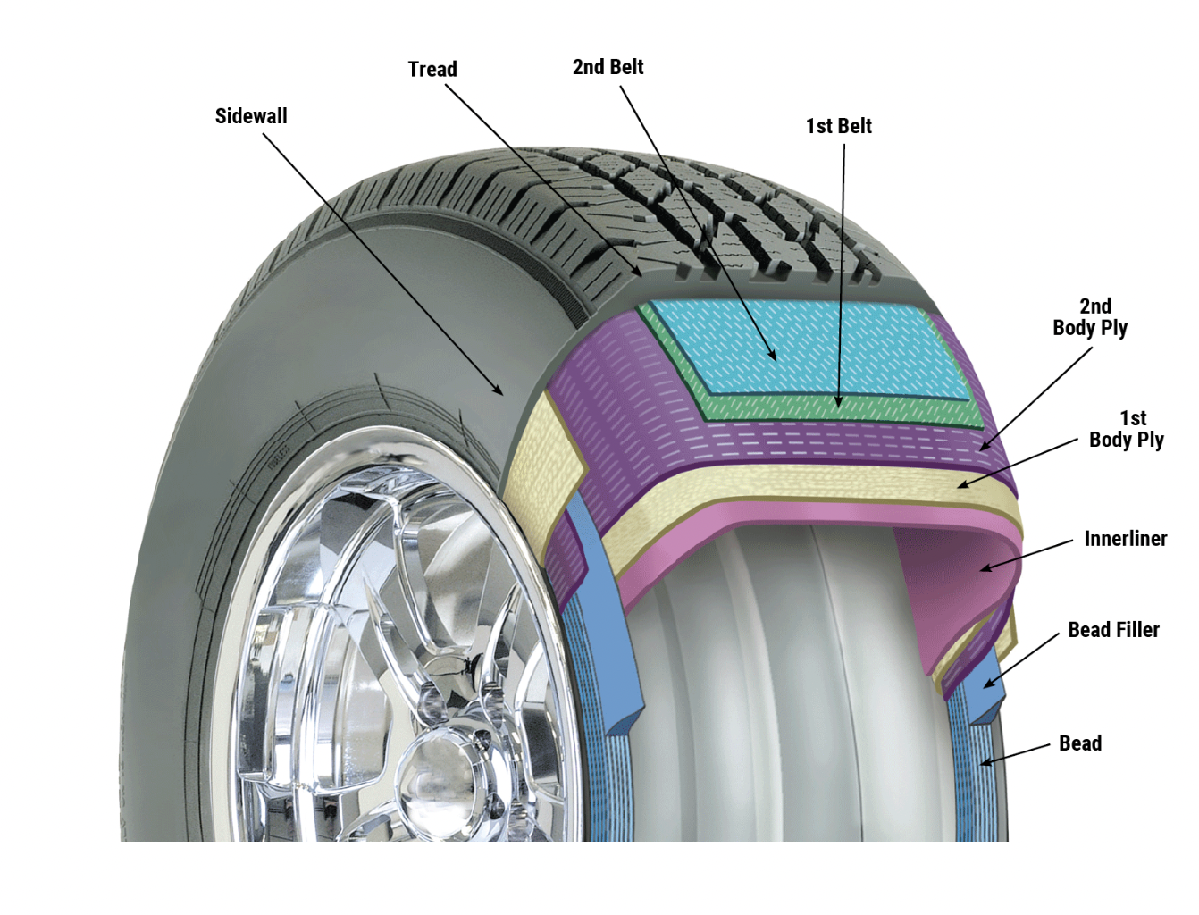
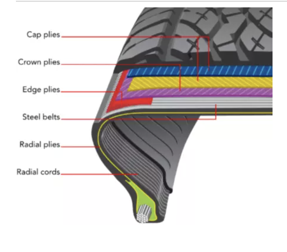
The bead wire, the cords running from one bead wire all the way to the other, the steel belts and the rubber tread area. There are many other parts to a tire, but these are the important ones we need to worry about here. In a radial tire, the cords are oriented radially outward from the bead wires. This is what gives radial tires their name:
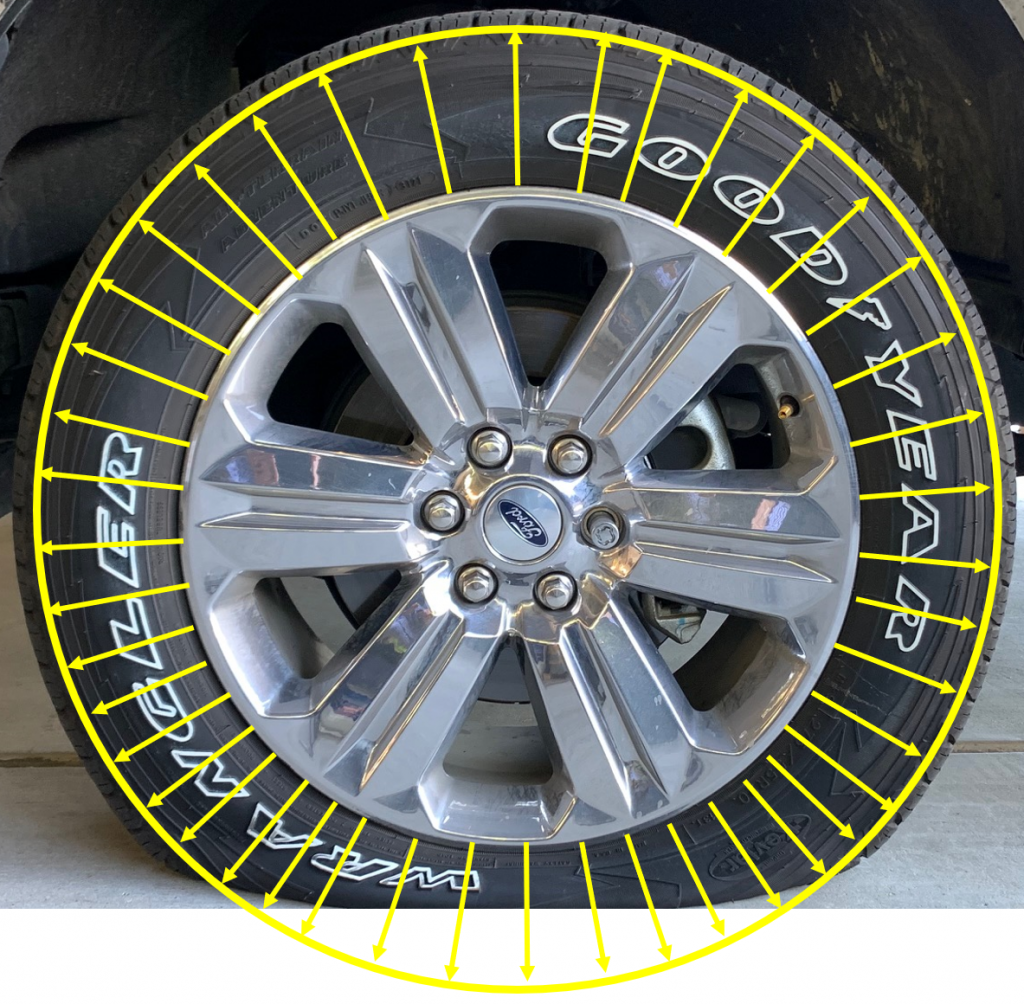
In an undeflected tire, all the cords are oriented like the yellow arrows in the image above. These cords connect the bead wires, which hold onto the wheel, to the steel belts and the rubber tread. Look closely at the steel belts, they are made up of many wires, and as you would imagine, these wires while very flexible, are also very strong. It is very difficult to stretch a steel wire without breaking it. Similarly, it is very difficult to shorten a steel wire by compressing it.
What this means is that when a tire is deflected by the weight of a car, the steel belts that used to form the green arc we saw before, now have to shorten to form the red chord. The belts don’t want to do this, and the result is that the extra belt length represented by the difference in length between the green arc and the red chord has to go somewhere. This “somewhere” is into the rest of the tire. The extra belt length gets pushed up into the rest of the tire, and to accommodate this length, the rest of the tire actually grows slightly. The diameter of the un-deflected portion of a car tire is just a little bit larger than when the tire is not supporting any weight.

In the image above, yellow shows the shape of the undeflected tire while red show the shape when it is supporting the weight of the tire. It’s exaggerated here but you get the idea.
As the extra belt length gets pushed up into the rest of the tire, the cords that connect the belts to the bead wires have to shift along with the belts. As we saw before, the cords in an un-deflected tire run radially outward from the bead wires. But, as the tire is deflected, the cords closest to the road get skewed by the movement of the belts:

You can see how the yellow cords have shifted to the positions shown by the green arrows. In this deflected state, the cords are no longer running radially outward from the bead wires. This is what we mean by the de-radialization of a tire. The cords that used to be radial, are no longer radial. They have been de-radialized.
Of course, skewing the cords like this takes energy. The cords don’t want to de-radialize. They want to stay right where they are and the energy it takes to push the cords and the belts out of their normal places has to come from somewhere. And there is only one energy source in a vehicle: the powertrain. As the cords and the belts get pushed out of their normal places by the rolling action of the tire, the powertrain has to work harder to overcome the energy that is lost due to everything that is happening inside the tire. It’s called rolling resistance, and it is a key concept to understanding aligning moment.
Aligning Moment
When a tire rolls down the road in a perfectly vertical position, the weight of the car compresses both the inner and outer tire sidewalls approximately the same amount:

And, as we learned earlier, this compression of the sidewalls causes de-radialization of the cords in the sidewalls. This de-radialization absorbs energy, and since both sidewalls are compressed the same, we would expect the de-radialization of each sidewall to be the same and therefore the energy absorbed by each sidewall to be the same as well.
However, if we now tilt the tire at some negative camber angle, the compression of the inner and outer sidewalls is now not the same:

Now, since the two sidewalls are not compressed the same, we would expect the de-radialization to also not be the same. We would expect to see much greater de-radialization in the inner sidewall than the outer. This would mean that there is more energy absorbed by the inner sidewall. This increased energy absorption would mean that the inner sidewall would generate more rolling resistance than the outer. This diagram from “The Multi-body Systems Approach to Vehicle Dynamics” by Michael Blundell and Damian Harty helps to illustrate the point. The top half shows the tire looking from the front while the bottom half shows the outline of the contact patch looking from above
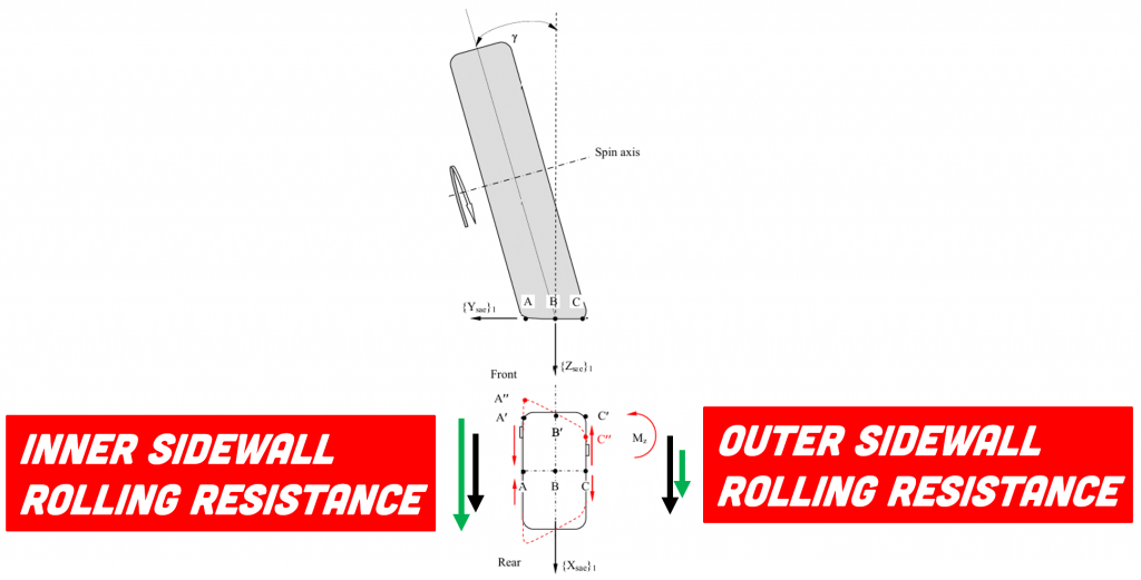
When a tire is moving at zero camber angle, the rolling resistance of the inner and outer sidewalls is equal, as represented by the black arrows. But, when there is a camber angle, the rolling resistance is not equal, as represented by the corresponding green arrows. The difference in rolling resistance between the inner and outer sidewalls causes a torque to be generated (Mz) which wants to steer the tire inward.
But there is another factor going on here. Imagine two points, point A and point C, where point A is located on the inner edge of the tire and point C is located on the outer edge directly opposite point A.

When the tire is rolling at zero camber angle, points A and C will come into contact with the ground at the same time. The diagram below shows what I mean. At zero camber angle, point A and C touch the ground at points A’ and C’ in the diagram.
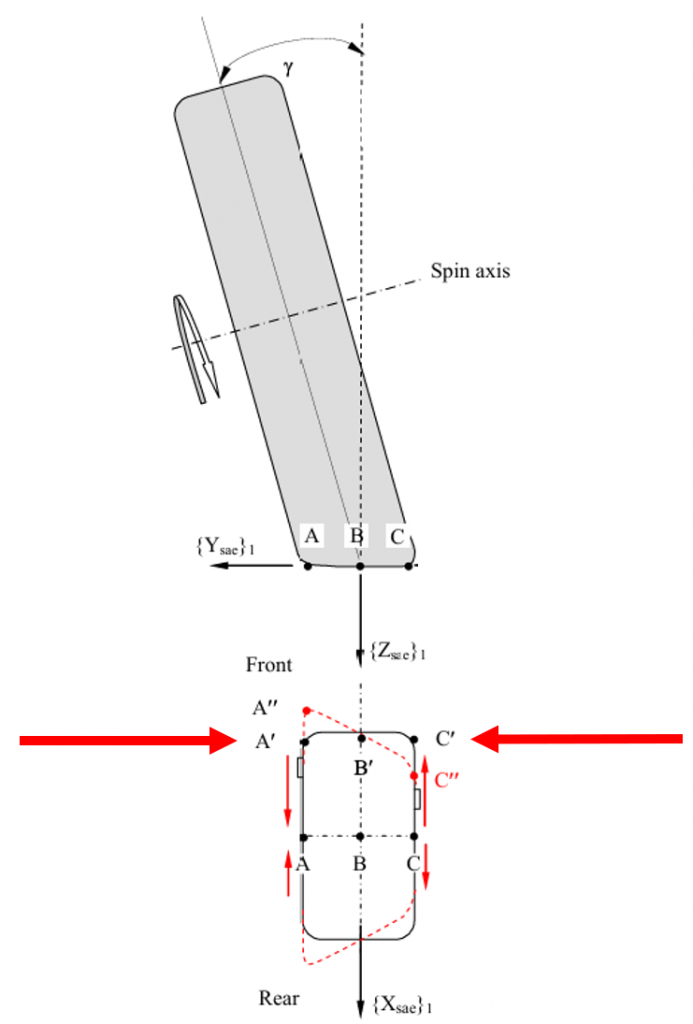
However, if the tire is rolling at some camber angle, then point A will come into contact with the ground before point C does (A” and C” in the diagram). When point A hits the ground, it gets “stuck” to the pavement while point C is free to keep rolling further along before it also gets “stuck” to the pavement. However, the belts that make up the main structure of the tire don’t want points A and C to be out of line with each other. They try to pull point A from position A” back to A’ and push point C from position C” to C’. This pushing and pulling throughout the contact patch also creates a torque in the same direction as the rolling resistance.
Together, these two phenomena try to steer the tire inward. The right side tire tries to steer left and the left side tire tries to steer right. When you’re driving straight down a flat road, none of this is a problem because the effects from the left tire and the right tire cancel each other out and the steering system keeps both tires facing forward. However, each tire is constantly trying to steer and push the car to one side or the other. When the road is not flat (i.e. there are bumps in the road), then the left and right side forces may not be equal and the car feels like it wants to steer by itself. This is especially true for wide tires when there are ruts in the road. In this case, the shape of the road puts unequal upward pressure on the inner and outer sidewalls and while the camber angle of the tire isn’t changing, the effective angle of the road is. The effect is the same. The angle between the road and the tire changes and the steer effect this causes can be quite strong.
Blundell and Harty call this torque a “self-aligning moment” caused by the tire camber angle.
By now, some of you may be screaming at your screens because from the beginning I promised to talk about a “thrust” which usually means a force. So far, all I’ve talked about is a torque and those are clearly NOT the same thing. Rest assured, there is yet another crazy thing going on in tires and this one actually does create a force.
Camber Thrust
When a tire sits vertically, the weight of the car pushes straight down on it. The cords at the top of the tire, which are supporting the weight of the car, are pulling straight up on the bead wires that are holding the wheel. The forces in the tire and the weight of the car are aligned with each other and balance each other.

But, if we tilt the tire to some camber angle, the forces in the upper cords will tilt as well.
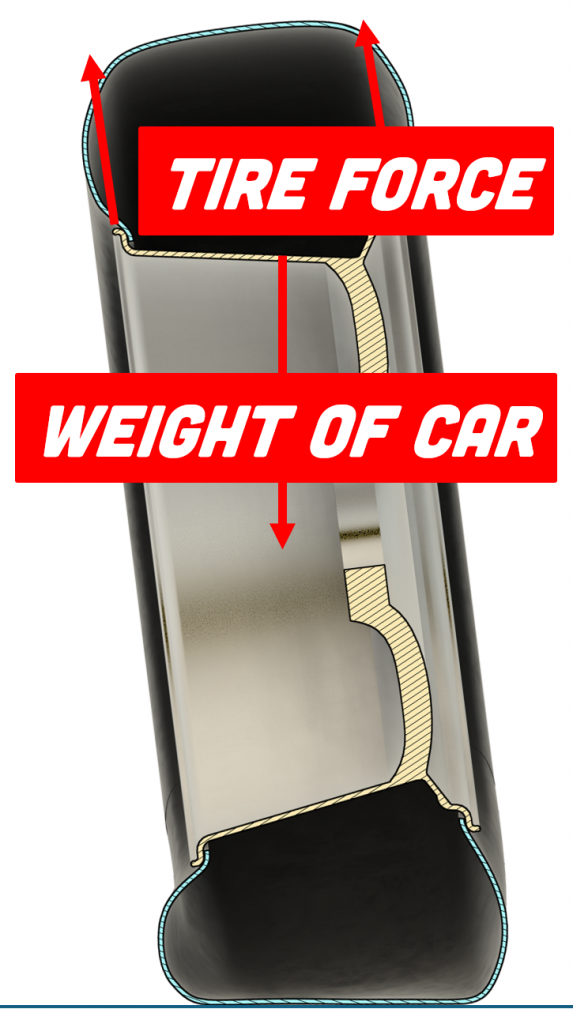
This means there is now an angle difference between the force in the tire and the weight of the car, which will always be vertical since gravity is always vertical.

To better understand how this impacts the car, it helps to think of the force in the tire not as a single force but instead as the product of two forces at 90 degrees to each other. Engineers call this “breaking down the force into its component vectors.” And the result in this case would be a vertical force equal to the weight of the car:

…along with a horizontal force at 90 degrees to it:

This horizontal force is called the “Camber Thrust” and it is directly related to the camber angle and the weight the tire is supporting. Increase the angle of tilt…

…or increase the weight of the car…

…and you will increase the size of the camber thrust force. Notice that this force is pushing in the direction of the tire’s tilt. The tire is not just holding up the weight of the car, but it is also pushing sideways against the car.
So, now we have two forces coming from the tire as a result of camber angle: the aligning moment and the camber thrust. Both forces are trying to push the car in the direction of the camber angle and the suspension and steering system are constantly fighting against them to keep the tire rolling in a straight line.
Race Car Camber
But what does this have to do with the high front camber angles we see in some race cars? A car has two front wheels, and if they are both cambered the same amount then the forces coming from the left and right sides will be equal and opposite and will just cancel each other out. What’s the point? The point is that while the car is going in a straight line, the camber thrust and aligning torque coming from the right and left sides will indeed be equal and cancel each other out. But, when the car enters a corner, the cornering forces cause a weight transfer to the outside tires.
The vertical force on the outside tires just got much higher than the inside tires, and since camber thrust and aligning torque are a function of the vertical force on the tire, the forces coming from the left and right sides are suddenly no longer equal. They become much greater on the outside tire than the inside

And this helps to push the car into the turn. Adding camber to the front suspension creates a force pushing in the direction of the turn and a moment that wants to steer the tire further into the turn. Both help to turn the car into a corner and make it more responsive to steering.
Camber in Street Cars
While these high front camber angles help the car turn in more sharply, it is possible to have too much of a good thing. A sharp turn-in is great if you are on a race track with lots of tight turns, but if you are trying to go in a straight line, the car becomes nervous. Any small undulations in the road or even tiny steering inputs will cause the car to dart in one direction or the other. This is why you don’t see them on normal street cars.
High camber will also cause uneven tire wear since there is much higher pressure on one edge of the contact patch vs. the other. Camber angle in street cars then becomes a trade-off between steering performance and tire wear, so you usually see about 0.5 to 1 degree of negative camber in the front and between 1 and 2 degrees negative camber in the rear of most cars.
The reason why there is a difference between the front and the rear is that a little extra camber in the rear helps add understeer. Understeer in a car is desirable because if you lose control, you want to run off the road nose first. That way if you end up hitting something you hit it with the front which is the softest, most energy absorbing part of the car. While camber thrust in the front helps to turn the car into a corner, camber thrust in the rear resists turning. It adds a momentary bit of understeer that helps to “support” the rear suspension as the car is turning in. It makes the car feel more planted and keeps the rear from stepping out.
Tires are immensely complex devices. They are definitely not just round and black. They are by far the most complex part of the suspension system but unfortunately also the most mis-understood.
Top photo: FCA


I have 3 degrees negative camber on my velomobile for most of the same reasons race cars do:
https://i.imgur.com/j75uGn7.jpg
It can do donuts without tipping over.
Next, explain why olde timey race cars with straight axle front ends used to run so much positive camber…
It’s a good question I don’t have the answer to. Perhaps it has something to do with tire technology at the time. One thing it would have done is significantly reduce the scrub radius since the steer axes of those suspensions were far inboard. It would have reduced steering efforts quite a bit.
Wow, much more depth than I expected when I read the title and clicked on the article. I’ll definitely come back when I have more time to digest the concepts that are new to me!
Take your time. I’m here all week.
Always enjoy your articles, and visual aids. Something that bothers me about both articles is a lack of accounting for the dynamics of internal air pressure and how that fundamentally changes how the tire responds as a system. I’m not arguing against your points, but feel it comes across as a fragmented understanding.
I ran -3.4* front and -2* (maybe -1.5*, can’t remember) rear camber on my Cramro 1LE for the track. Didn’t actually wear too bad for road use, but if you didn’t max the negative camber on the front it blew through the outside tread pretty damn quick on the track.
In my opinion, camber looks cool because of race cars. Stance and the Japanese bozozuku? are taking the aesthetics of race cars to the extreme. Without race cars, stance would just look like a problem in alignment.
My wife somehow survived 34 years on this planet until THREE weeks ago she finally asked me “why does that Nissan look broken?”.
It was stanced.
I explained the Carolina squat as a necessary side-bar – she was filled with rage.
Interesting, I didn’t know about those dynamics. I asked an alignment shop to get as much negative front camber on my FiST as they could (the only adjustment is the natural slop of the suspension) and ended up with about 1 degree on both sides. Helped reduce the wear on the outside of my autocross tires, I’m assuming that’s partially because with body lean on sharp corners the contact patch is a little flatter? Didn’t solve the problem completely though – probably would need more adjustment for that.
1st gen Explorer are great to explore camber as the front suspension has insane camber curve, so much that body roll decides how it’s handling. Too much or too little and the nose washes out.
One of the few places outside of a swing axle you can hit -4 degrees camber.
Also not mentioned is how useless at putting down power a couple of degrees of camber is. My BRAT was limited on the skidpad because it had 2 degrees positive camber and loved to dump its two digits of torque out. So don’t go fwd racing w a open diff please.
Didn’t those Explorers have the “Twin I Beam” on the 4wd models? They are essentially swing axles.
Twin traction beam is iirc the 4wd version.
Both as the twin I beam was on the 2wd Explorers (and Rangers) and TTB on 4wd.
This is another informative article on the dynamics of suspensions.
The diagrams really do help to visualize the description.
Now, I understand better why those lowered Geo Trackers in the 90’s with negative camber appeared to be so twitchy on the road.