Electric motors have been around for the better part of two centuries now, so you might think there’s nothing new left to discover about them. That’s not the case, however, as it turns out Kia has pulled off some nifty tricks with the propulsion unit for the EV9.
The team over at Munro & Associates has been pulling apart Kia’s new full-size electric SUV. Now, we get to see a teardown of the EV9’s rear motor which reveals something special. The Korean automaker has pulled off a bit of a world-first that could net some serious efficiency gains.
The video gives us a quick montage to show the disassembly process for the rear drive unit. Ultimately, though, it’s the motor’s windings that are the primary focus. To explain why this it’s so special, Munro tapped lead electric machine development engineer Paul Turnbull to give us the low-down.
Cleverly Using The Motor To Boost Voltage From 400V To 800V
Before we start, we should just cover off some terminology. First, when Turnbull says “electric machines,” he’s basically saying “motor.” Beyond that, you should read our deep-dive on how EVs work, and you may want to brush up on some basic motor terminology; I explained it in last week’s article on the Ford Mustang Mach-E, but I’ve quoted it here for your convenience—along with diagrams!
What’s a stator? Well, it’s the big metal part of the motor that is, as the name implies, stationary. A stator is typically made of laminated plates of special steel that reduces eddy current losses, and is the structure that holds the windings. The stator windings are basically coils of copper wire wrapped around the stator core to generate the rotating magnetic field that makes the motor spin. If you’ve ever wound a coil of wire around a nail to make an electromagnet, you’re familiar with the concept. Windings in EV motors tend to use more advanced geometries and thicker wires, but the concept is the same. Wrap a conductor around some metal, run some current through it, and you’re generating a magnetic field.
[The rotor] is the central spinning part of the motor. The rotor has permanent magnets on it, so when the changing currents in the windings create a rotating magnetic field, the rotor spins in turn. It’s the job of the motor’s control electronics to energize and de-energize the separate windings in the right sequence to make the rotor spin. There are usually three sets of windings, or “phases,” that have to be switched in the right order to make the motor turn.
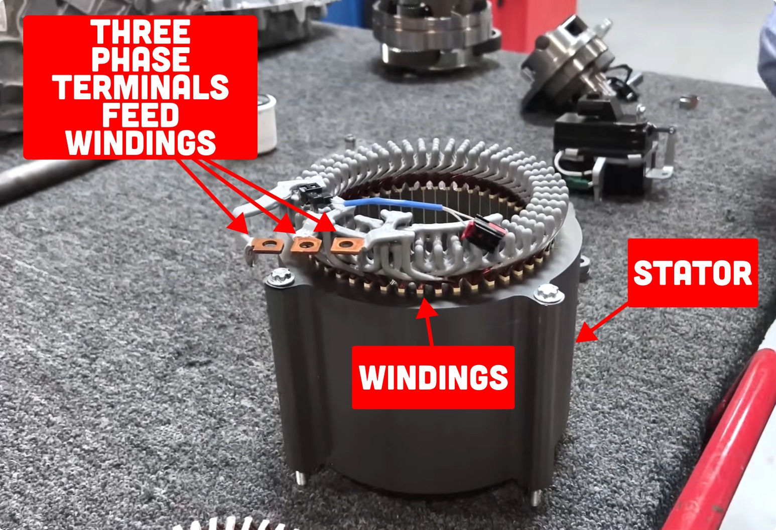
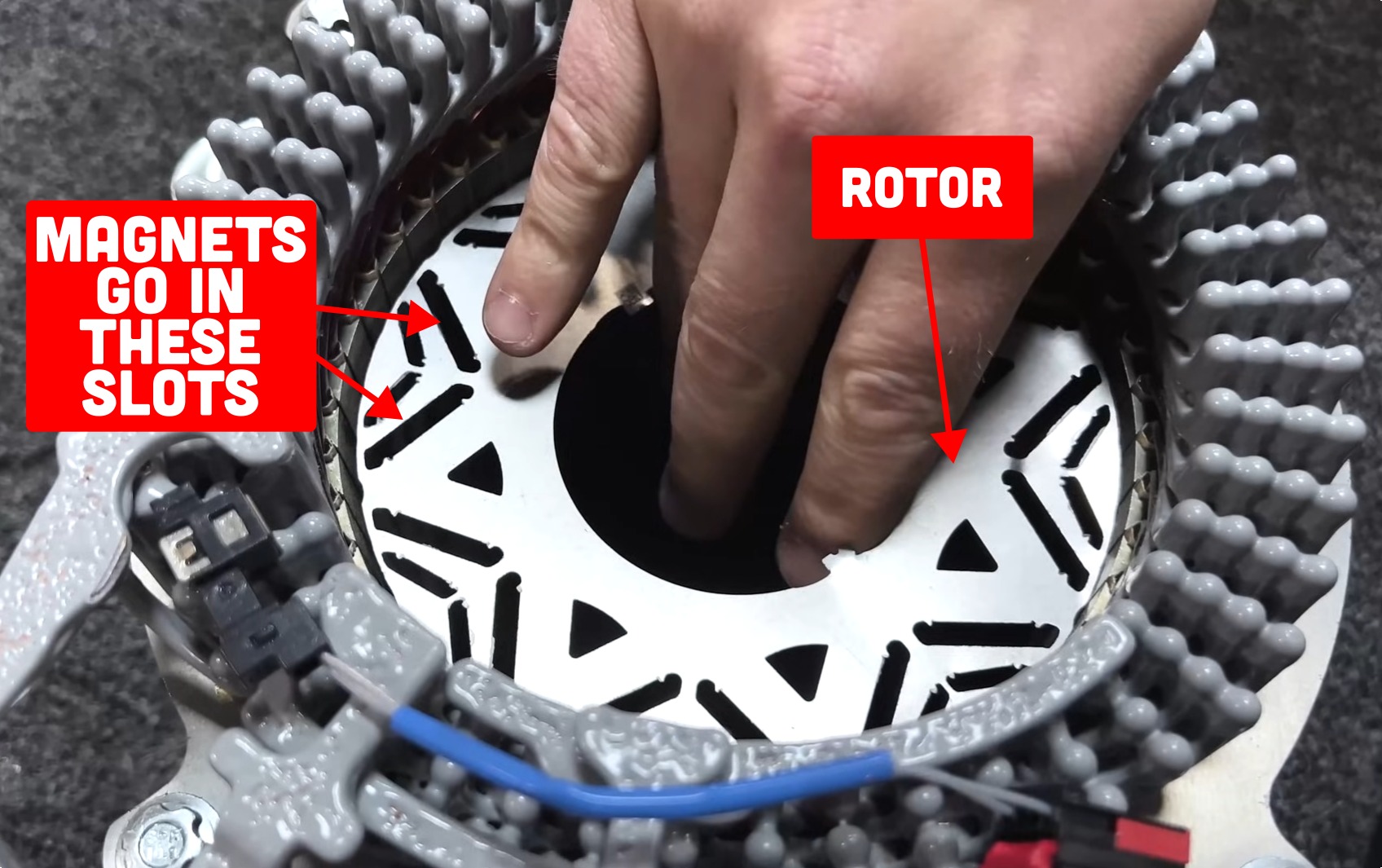
Okay, so back to the video. It begins with some interesting context — Turnbull shows us a motor out of the Hyundai Ioniq 5. He notes that while most such EV motors have three terminals, this one has four. It allowed Hyundai to pull off a nifty trick. “They’re using the inductance of the motor as a part of the boost converter in their charging system,” Turnbull explains.
Confused? It’s actually quite simple. Basically, Hyundai’s EVs were using 800-volt battery systems, but many chargers only put out 400 volts. To charge properly, the needed to use a device called a “boost converter” to step the 400 volts up to 800 volts. The boost converter typically requires a large inductor—basically, a big coil of wire. Hyundai realized the motor was full of large coils of wire, and thus the windings could act as this inductor instead. The motor isn’t otherwise used when the vehicle is stopped and charging, after all. It just had to add an extra terminal to make it possible. This saved the company the cost of including another expensive inductor in the boost converter circuit.
What’s a Dual Stage Motor?
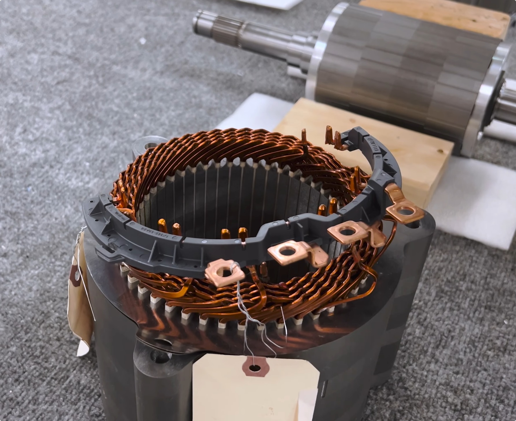
Look at the Kia EV9, though, and things have gotten even fancier. It’s now got six connections! “They have both the beginning and the end of each of the three phases connected to the inverter, and that gives them full access to the winding configuration of the motor,” Turnbull explains. “What this system does when you have all six connections coming up to the inverter, it allows you to reconfigure the motor in one of two different configurations – either wye, or delta.” So what does that mean? Well, it’s all about how the windings are connected.
The EV9 rear drive unit. The rotor has already been removed in this shot.
A motor has three sets of windings—or phases, if you will. Each winding is essentially a long length of copper wire that’s been wound around the stator to create a magnetic field to turn the rotor. Normally, you have three connections to the three windings on the motor. These hook up to the inverter/motor controller. The other ends of the windings are usually permanently connected in one of two configurations—delta or wye. In delta configuration, the end of each winding is connected to the start of the next. It makes a triangle if you draw it as a schematic, so it’s called “delta.” Alternatively, you can connect the other ends of the windings together in a single point. This makes a Y shape if you draw it out, so it’s called “wye.”
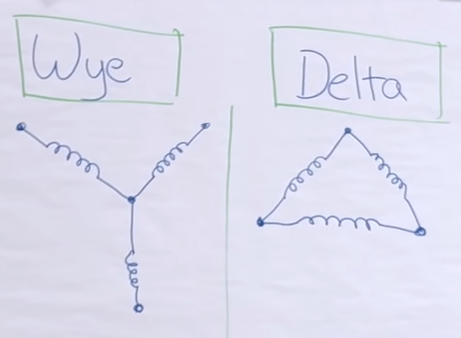
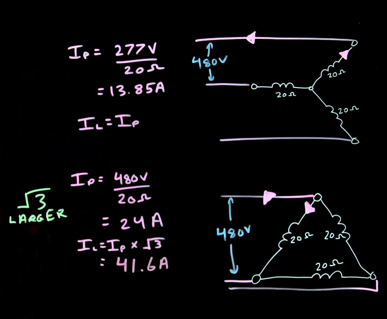
If you want a deeper explanation of the differences between wye and delta windings, I can recommend these videos from Electrical Trades Instructor/podcaster Zack Hartle. However, they’re intended for an audience already very familiar with electrical topics. If that’s too complex, I’ll spell it out in simpler terms below without all the electrical mumbo jumbo.
An Electric Motor ‘Changing Gears’
Depending on the winding configuration you choose, the motor will have different characteristics. Here’s a simplified explanation. For a given input voltage, you would typically choose a wye winding for a motor that’s more efficient at low speed. You’d choose a delta winding for more power and efficiency at high speed. However, Kia realized that if it exposed both ends of the windings, it could use switching hardware in the inverter to change the winding configuration on the fly.
Munro’s Turnbull notes that wye-delta switching is very common on industrial machinery. It’s often used on large motors in heavy equipment. They are often started with the windings set to the wye configuration, which limits the amount of current drawn by the motor. As the motor gets going, it can then be switched into the delta configuration, which draws more current but also offers more power and efficiency at higher speeds. It’s almost like an electrical equivalent of shifting gears.
Thus far, EVs haven’t used wye-delta switching due to the added complexity, but Kia has found a way to make it work.
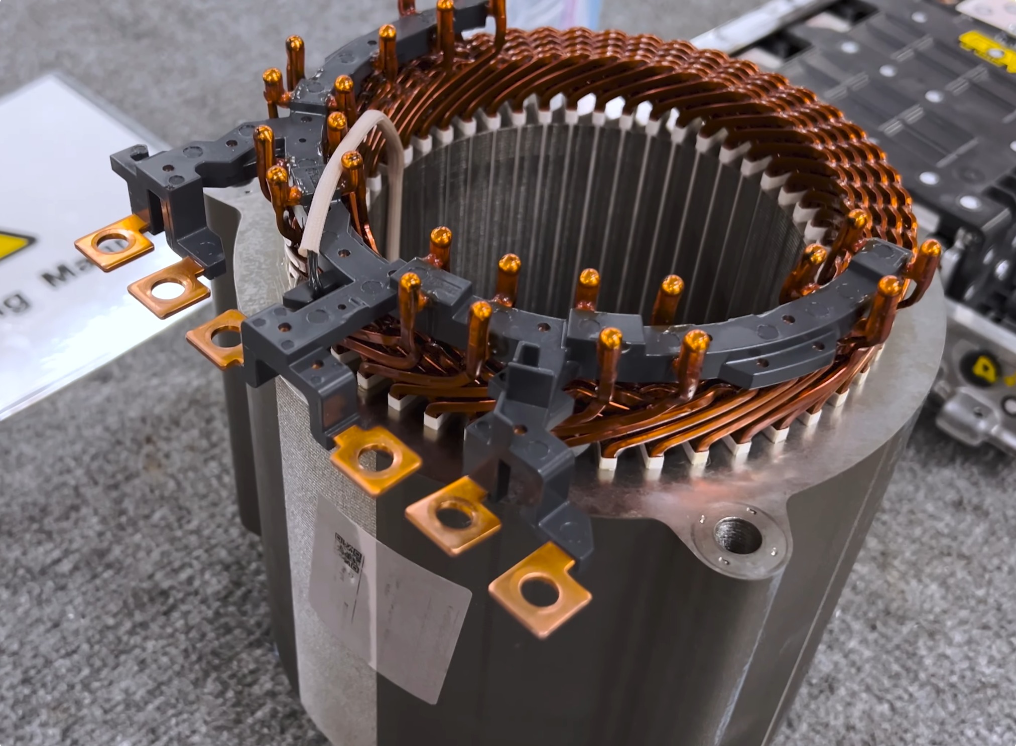
Turnbull refers to it as a “dual stage” motor as an easy way to understand it. “When you switch from wye to delta, the personality of the motor completely changes,” he explains. “When you connect the machine in wye configuration, it gets high torque, and it’s really great for low-speed efficiency.” Meanwhile, the delta configuration behaves quite differently. “If you connect it in delta… you end up with lower resistance in the winding, and you get much higher power from the motor, about 1.7 times the power,” says Turnbull. “You shift the high-efficiency point from low speed up to high speed.”
The result is a motor that performs better over a wider operating range. “Typically you have to design a motor with one physical connection and then you have to compromise between this low-speed and high-speed performance,” says Turnbull. “But with the EV9, they’re able to optimize for city efficiency in the wye connection, and then on the fly, this inverter is able to switch—with power running—to change it to a high-power [delta] configuration with high efficiency at highway speed.”
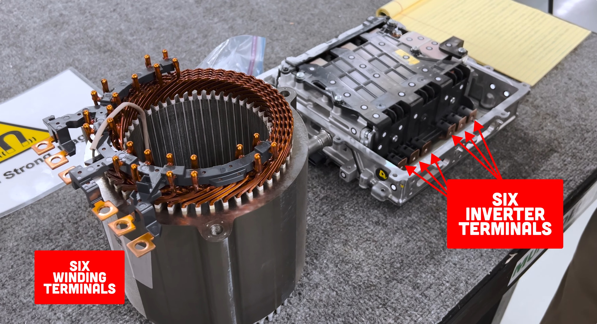
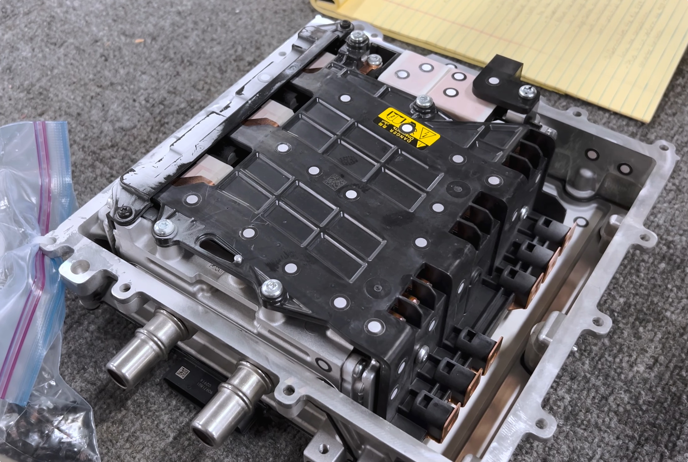
The switchover is handled by the semiconductors in the inverter itself. “It’s just a reconfiguration of the winding, and the inverter is able to smoothly transition from wye to delta.” Turnbull explains. “That smooth transition allows you to go from the high-torque, low end, get-off-the-line performance that you get with a wye connection, to, when you get up around 45 mph, you switch to delta… and then you get the high efficiency performance for better highway electric range.”
‘Brilliant’ and ‘Groundbreaking’
Noting that it’s “absolutely brilliant,” Turnbull expounds upon why we haven’t seen this before. Basically, it comes down to costs. “In the past, it has never been practical, because in order to do it, you have to have, in the inverter, two completely separate sets of switches,” he says. Basically, inside the inverter, there are a bunch of semiconductor switches, normally Insulated Gate Bipolar Transistors, or IGBTs. They’re responsible for switching battery power to the windings of the motor in the right timing to spin the rotor. However, if you have a six-lead motor, you need more IGBTs to control the connections between the other ends of the windings.
“The switches are the most expensive part of the inverter, and so there really hasn’t been a cost effective practical way to do that,” says Turnbull. “But now, these switches are coming down in cost.” Basically, now that EVs are becoming more popular, economies of scale are kicking in. It’s not cost prohibitive for Kia to throw in some extra semiconductors to pull off this neat little winding reconfiguration trick.
Oh, and remember that trick on the Ioniq 5 with the boost converter? Kia’s doing that here, too. Turnbull notes that the cost savings of using the motor’s windings instead of another big inductor really help. “With all that functionality built in, it more than pays for the extra set of switches in the inverter,” he says.
“This is an idea that has been kicking around in the industry for twenty-plus years and no one’s been able to come up with a practical way to actually implement this for a traction machine in an EV,” Turnbull explains. Basically, Kia’s pulled off a bit of a game-changer. “It’s the first that we’ve seen in the industry, a groundbreaking innovation that Kia has put on the road for us,” he says. “It’s something that I think a lot of the other automakers now are going to be looking at.”
Turnbull also credits the Kia motor for the quality of its construction. “I wanna give a quick shoutout to the supplier that made this motor… the supplier is Vitesco” he says. “Not every electric machine developer is able to do these bar wound interior magnet machines with this kind of quality.” He particularly highlights the construction of the windings themselves. “I want to point out the uniform spacing between the conductors, and how every single conductor has the same exact bend in it,” he explains. He also credits the quality of the welding, noting that these two factors are key to building a motor with excellent durability.
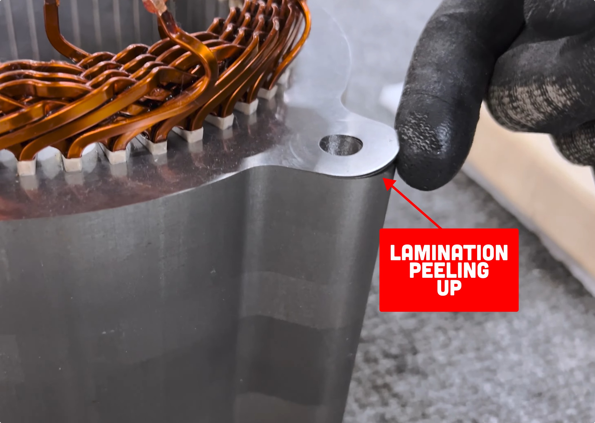
The laminations on the stator are solid, too. “On the older design [on the Ioniq 5], you can see that the lamination around the mounting points can sometimes bend up,” he says. “This has happened during our handling, but it can happen in [the manufacturing] process and that can cause some trouble.”
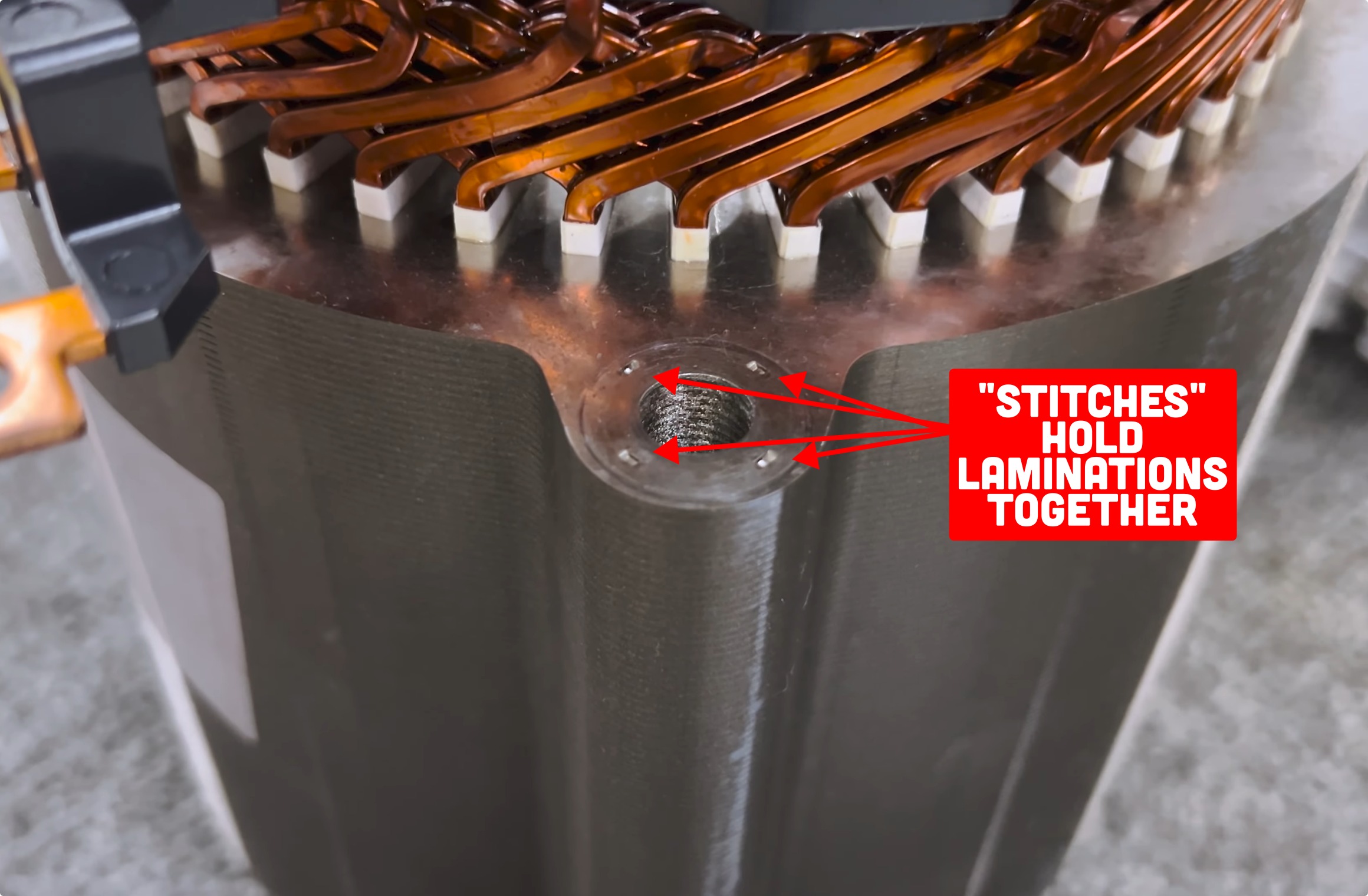
On the Ev9 motor, though, Vitesco has taken measures to improve things. “What they’ve done here is they’ve added four little… what we call stitches… where they indent the material to make one lamination lock into the next, to make sure the laminations stay put,” says Turnbull. “Little details like that are a sign of a supplier that knows what they’re doing.”
Ultimately, it’s no surprise we’re seeing innovation like this in the Kia EV9. It’s an important product for the Korean automaker, and it helps to be on the cutting-edge to do well in the marketplace. It’s also the kind of thing you’d never learn unless you completely pulled the vehicle apart. It’s hard to argue with the value of a good teardown!
Image credits: Munro Live via YouTube screenshot, Zack Hartle via YouTube screenshot


This was extremely informative! I thought “oh, my Tucson PHEV changes gears, so what… OHHHHHH, this is very cool!”
This reminds me of when Honda invented VTEC. Hyundai/Kia invented electric motor VTEC
Given (as the article points out) this tech. I.e. the abilities to switch the motor windings, which is incredibly cool btw… already exists in a lot of heavy equipment ev motors, it is applying the same tech. in a MUCH smaller format which is a heck of an innovation in itself.
Therefore very akin to the introduction by VW of direct injection in to automotive diesel engines (introduced I think 1st with the Audi brand in the mid 1990s with tdi), which likewise previously had only been implemented in heavy duty equipment.
This was an excellent article, well-written, and effective at explaining technical information to an audience that may not have a good electrical engineering background. Nice work, Lewin!
I say all of that so that my attempt at constructive criticism will be taken with the good faith and affection I intend. You use the word “basically” 8 times in the article: once in an embedded quote, but the rest in your own words. Your articles have great technical content, but it may be worthwhile for you (and your editors) to pay some attention to their language.
I’ve known about wye/delta motor configurations and series-parallel transitioning in electric traction — it’s a common and essential operating function in industrial equipment, electric railway applications, etc.
Today I learned that it hasn’t been widely applied in electric cars until now — which kind of baffles me.
Making a motor function well for both starting torque with protective current limiting as well as higher current/lower but continuous torque for sustained running and speed has been a solved problem for nearly a century. (Diesel-electric locomotives have used contactors to do this since at least the 1930s; the principle may have been used in industrial motors before then.)
A single-configuration motor in a vehicle is basically a brute-force approach. Advanced motor designs and battery technology makes it possible, and that’s a great achievement. But the efficiency gained from being able to change over the motor configuration based on the running demand ought to deliver non-trivial improvements in battery range and drivetrain efficiency that were being left on the table.
My guess, though, is that nobody wanted to introduce the kind of control complexity and need for additional electrical control equipment in cars if they could get away with it. A big selling point for electric cars initially was the lack of an engine taking up space, leaving the front empty for a “frunk”. All the motive gear plus the batteries were hidden away under the floor, with only the 12v battery and a seemingly small controller box under the hood. But higher-powered cars have required more cooling and control equipment anyway, to the point that the “frunk” storage is getting smaller or nonexistent anyway. At this point, there’s really no space penalty for adding in the additional necessary boxes to house more sophisticated inverters and control hardware. And maybe they’ve figured out how to ensure the efficiency gains cancel out the added weight of the additional electrical gear*, particularly if the battery can shrink a bit too and still maintain the same range?
*Weight has always been an engineering headache for electrically-propelled vehicles. Batteries are the 21st century version of the problem. Before that, it was just the weight of motors and power conversion/control gear for electric vehicles powered from trolley wires. Diesel-electric power also faced issues with weight; the diesel engine, generator, and running gear were largely fixed weights, so reducing weight of the rest of the electrical gear was one of the places worked on to improve power-to-weight ratios. Electric cars still face the same kinds of problems.
I’ve already seen similar done DIY in the small emoto and electric mini bike drag scene. Just use the same amount of power to the different sets of windings.