The engine is the beating heart of a vehicle. The sensations we gearheads receive from the combustion process activate feelings deep within our psyche. Like the goosebumps that come during the climax of your favorite song, the sounds from an engine can elicit that same unconscious flood of adrenaline.
In this article we are diving deep into the science behind how these sounds are made. It is a complex subject, and I’ll try to cover all the bases. We will review the physics that give an engine its unique sound signature, and the effect of headers and exhausts, intake noise, and more. At the end I hope you will have a deeper appreciation for how these complicated assemblies of metal and plastic gain a soul through their vibro-acoustic expression.
I’m Steve Balistreri, an engi-nerd from Detroit who’s worked in automotive NVH for around 20 years. During this time I’ve tested thousands of vehicles of every type from almost every manufacturer. I’ve always found it fascinating when mathematics and physics can not only capture, but explain and change the physical phenomena we experience when we drive a car.
How I Will Simulate Engine Sounds, Which Are Just Pressure Waves
Before we get started I need to explain a few things. First is the source for many of the engines we will be analyzing. As an NVH engineer, our goal is to measure the sound of the test object to the highest levels of accuracy. To do this we go to great lengths to eliminate any possible outside influence — testing in anechoic chambers that cost millions of dollars; transporting vehicles to test tracks across the country so they are measured in a quantified environment; following strict test procedures; and using expensive, lab-grade equipment that often costs more than the vehicle we are testing.
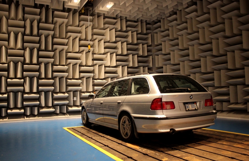
The engineering method that’s been drilled into my brain for the past 20 years had me dreading finding source-sounds for this article. I figured I’d have to scour YouTube for weeks to find quality recordings for each type of engine. Not only could there be any number of exhaust setups that would greatly influence the sound, but the location and type of recording device would be different for each video. What kind of microphone is it and what is its distance and position in relation to the exhaust tips? Are the microphones in an echoey environment like a dyno cell or garage? Is there wind noise or tire noise? Are there people talking or other vehicles driving by? Are they doing a slow and steady runup that is needed for good data, or are they just blipping the throttle randomly?
Trying to get a clean and true A to B comparison that you could draw conclusions from would be like finding two needles in a haystack in the middle of a tornado.
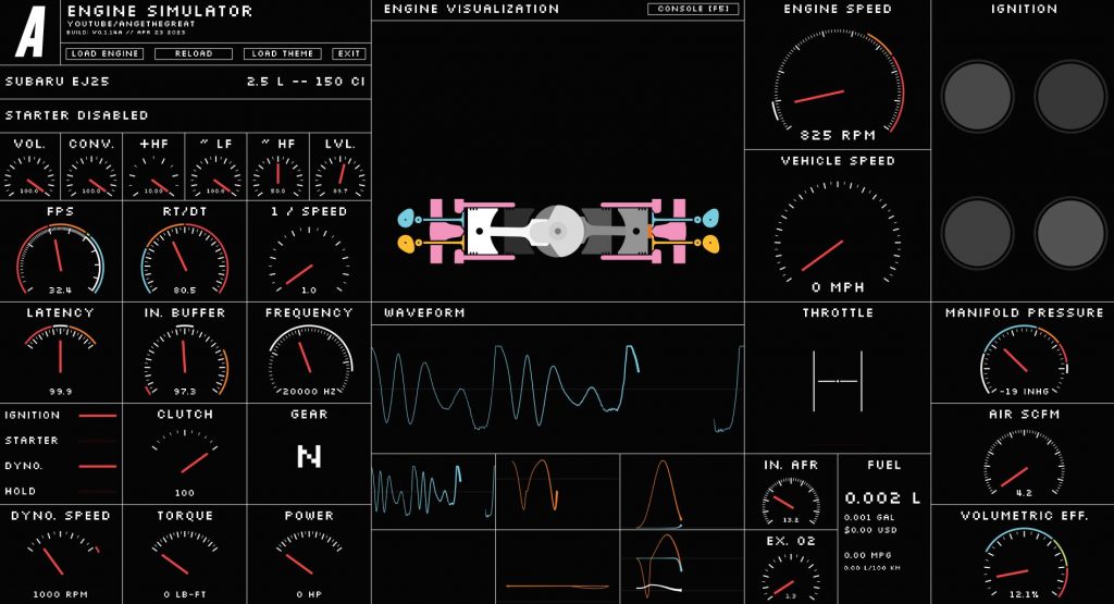
Worried I’d be out of luck, I searched for other options and happened upon an engine sound simulator by AngeTheGreat. I was doubtful there would be a simulator out there worth using, but the more I read about ATG’s simulator the more impressed I was. For example, the engine parts you see whirling around in the display aren’t just some cool, preloaded animation. It is a live rigid body simulation that is figuring out the physics in real time, and the physics gets deep. This thing is doing fluid dynamics computations, flame propagation, inertia, friction and airflow calculations. Just looking at all the variables that go into making an engine model made my head spin.
All that these equations are calculating is the resulting pressure wave sent through the exhaust system (the sound). I can modify all sorts of parameters on the fly to see their effects, which is impossible any other way. Ange is a programmer, YouTuber, and gearhead. As a kid he was frustrated by the unrealistic engine sounds in the video games he played. After a ton of research, he started his simulator project. Ange has physically built engines, so he knows his stuff. You can support him on his Patreon here. You can also see a video about the simulator below; it’s pretty mind-blowing.
In the end, the beautiful songs our beloved engines make all boil down to cold, hard physics. You can’t get much better than Ange’s engine simulator when it comes to modeling the key components of an engine’s sound. We now have true A to B comparisons, without worrying about exhausts, environments, how it was recorded, the sounds of crowds wooing or Mustangs crashing in the background. We will be looking at some real engine sounds in this article, but for a lot of the comparisons another method was needed. So hats off to Ange for building this thing. Make sure to download it, check it out, and send him a few bucks on Patreon.
Let’s Talk About ‘Orders’
Our first lesson is how to interpret the language and the graphs we are using in order to tell these motors apart. To do this we will review some NVH basics. I’ll quote myself from my Active Noise Canceling article:
The sound wave graph we are familiar with is plotting the pressure of the medium at a specific point (like on the diaphragm of a microphone). The peak of the wave is the maximum pressure, the trough is the minimum pressure, while the middle is regular boring atmospheric pressure. Where the air particles are squished together, the pressure is high. Where the air particles are spread out, the pressure is low.
The amplitude is the height of the wave and the depth of the trough. The length of the wave is, you guessed it, the wavelength. The wavelength is directly related to frequency. Since sound waves move at a constant speed, having shorter wavelengths will result in more waves crashing into your ear drums ie. a higher frequency. Long wavelengths result in fewer crashes or a lower frequency.
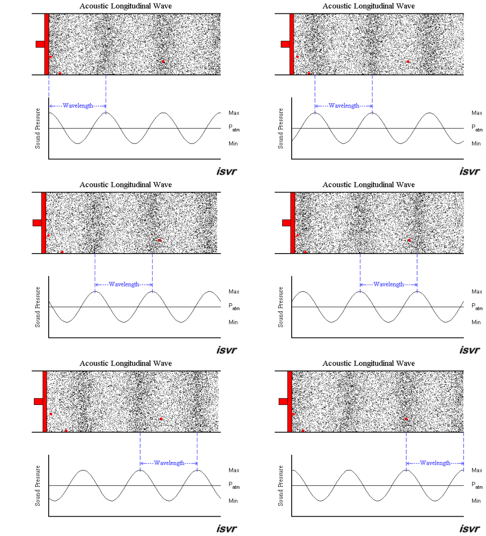
These pressure waves contain many frequencies all scrunched together. Luckily for us, the frequencies of the rotating components in an engine or transmission are easily calculated and tracked with something called “order analysis.”
Let’s pretend we have a gear with 10 teeth. Every time that gear rotates, there will be 10 regular, evenly spaced “events,” or impacts, per rotation that will generate noise and vibration — basically each time a gear tooth rolls in and out of mesh with the tooth of another gear. If that gear is spinning at 600 RPM, or 10 rotations a second with 10 events per rotation, it would create a noise at 100 Hz. Hertz is the unit of measurement for frequency — basically the number of cycles, or waves per second. We NVH engineers would call that 10th order noise since there are 10 events per RPM of that gear. Here is the math for that:
Since Hz measures oscillations per second, you need to convert your rotations per minute to rotations per second, so divide by 60:
600 RPM / 60 = 10 rotations per second
Since there are 10 gear teeth ie. 10 “events” per rotation, you multiply the number of “events” per rotation times the number of rotations per second to get the frequency:
10 events per rotation * 10 rotations per second = 100 Hz sound and/or vibration.

Orders vs. Frequency
Here’s another way to explain order analysis that may be more relatable. Imagine a six bladed fan spinning on your desk. For reasons you can’t explain, you are drawn to stick your finger in that fan. Your poor digit is being struck six times per rotation, creating a sixth order noise. If you change the fan speed setting from low to high, the frequency will increase, since your finger is getting smacked more times per second. But it is still being hit six times per fan rotation, and the noise is still 6th order even if it is higher in frequency due to the RPM increase.
The RPMs of our typical test subjects are constantly changing, whether they are engines, transmissions, axles, or electric motors. When these parts get more complicated with multiple gear sets, bearings, shafts spinning at different speeds due to different gear ratios, tracing a frequency to its source gets a lot more difficult. If we have a noise at 578 Hz in an automatic transmission, which gear out of the dozens that are whirring away at different speeds is making that noise? How many teeth does each gear have, how many rollers in each bearing, what speeds are they spinning relative to each other? And when the RPM goes up or down, so too will that frequency, and we have to start our calculations all over again.
To keep the engineers from going insane and wearing out our calculators, we talk about orders instead of frequency when describing the NVH of rotating parts. Our 100 Hz gear noise we calculated in the equation above would be called 10th order since its 10 events per rotation. If that gear were spinning at 1200 RPM and making noise at 200 Hz we’d still call it 10th order. If the speed were sweeping from 10 to 10,000 RPM we’d call it 10th order the whole way up. By indexing our measurements and plotting our graphs against RPM instead of frequency we eliminate this variability and have a much easier time getting a handle on complex noise events.
If we have the kinematics of the part we are testing (a model of all the gears, shafts, and the number of teeth), we can look at a complicated spectrum, point to a peak and say: “This is from the idler shaft being out of balance,” or “this gear is out of round,” or “this is the 2nd harmonic of this engine’s firing frequency.” It is a powerful tool, and what we are going to use for this study.
The Plots
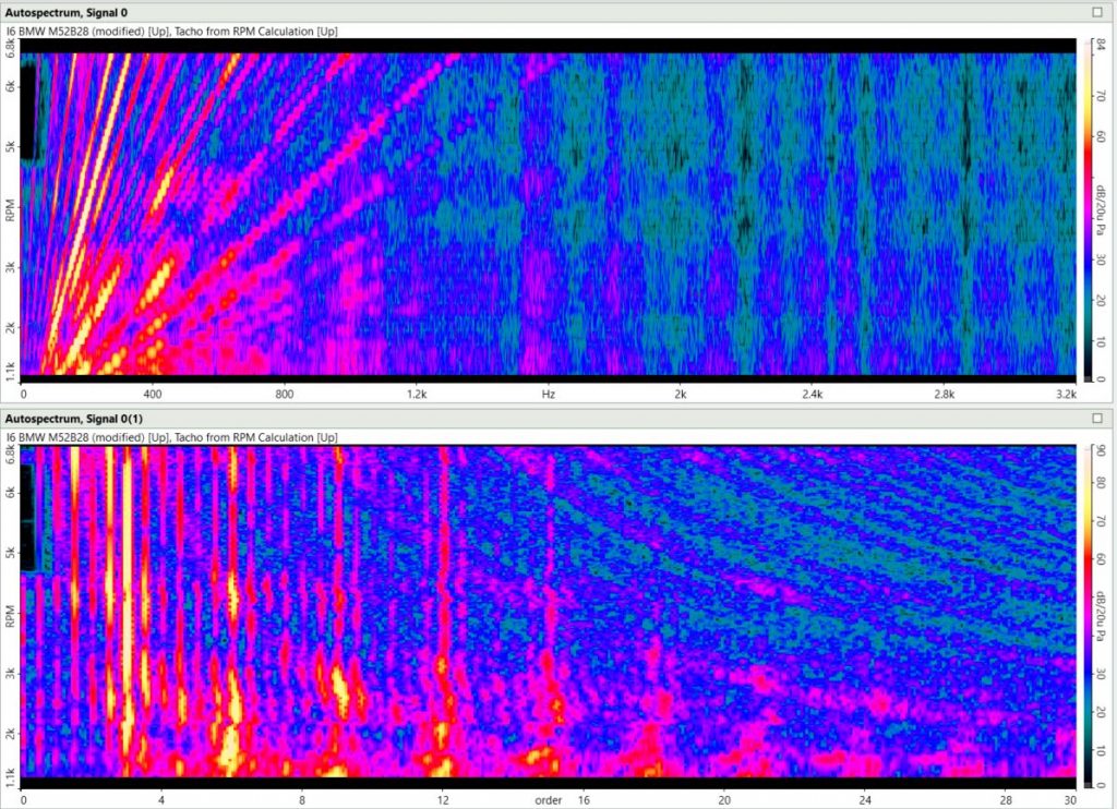
Now to explain our plots. This is going to get a bit complex, but don’t be discouraged, because you don’t have to know all of this exactly. The colorful plots that look like the black light tapestry hanging next to the Sublime poster in your cousin’s dorm room are called waterfall plots, or color maps depending on your preference. They show the frequency levels through the entire RPM ramp, creating a visual picture of the sounds you are analyzing. The vertical Y axis is RPM, while the horizontal X axis is either frequency or order. The colors represent the loudness of the noise at that particular point in decibels (or dB). This process that takes a sound wave and breaks it into its component frequencies is called a Fast Fourier Transform or FFT, so the frequency spectrums are often called FFT spectrums.
The order plots are showing the same data as the frequency plot, but with a different X axis. In the order plot the sounds created by the engine are straight vertical lines. In the frequency plot, the engine orders are diagonal. This makes sense, as we’ve discussed already, because these engine frequencies are increasing with RPM, because there are more rotations and pressure pulses per second. Noises that have a constant frequency are straight, vertical lines in the frequency spectrum because the frequency doesn’t change. In the order spectrum they are curved lines, because the whole spectrum is being warped to make these diagonal, increasing frequency lines vertical. You can see this in the higher frequency dark purple / blue vertical lines on the right of the frequency spectrums below. In the order spectrum they are curving from the top of the plot to the right side.
The next plot is an order plot that eliminates the RPM axis. It shows the average decibel level (or loudness) of each order through the whole RPM ramp. If you think of the above order spectrum plot like viewing a mountain range from an airplane, the order plot below is viewing it from the ground with the orders sticking up like little peaks of sound. This plot is useful because you can overlay multiple engines on the same graph to make comparisons, which isn’t possible with a waterfall plot.
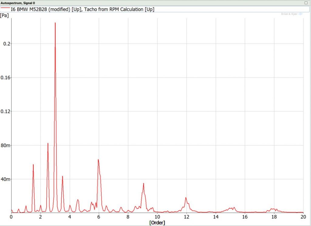
So to tie it back to engines; instead of gear teeth meshing, the “events” you hear streaming out of your tailpipe are pressure pulses made by pistons pushing exhaust gasses out of the combustion chambers, which occur regularly at very specific points in the engine’s rotation. These pulses create different frequencies or orders based on the engine type. The combination of orders creates the musical “chord,” which is the distinctive sound of your favorite engine.
Combustion Noise Isn’t The Same As Exhaust Noise
It may surprise some of you, but the baritone roar of your favorite muscle car isn’t the sound of the explosions going off inside its V8. The ignition of the fuel and air mixture in the cylinder creates combustion noise, which is totally different from exhaust noise. In fact it sounds pretty annoying. Let’s have a quick lesson on combustion noise before we get to the good stuff.
Compared to exhaust and intake noise, the combustion noise is much quieter when you stand next to your car. This makes sense, as it’s happening inside a heavy, tightly sealed hunk of metal. You can hear it when you stick your head under the hood — it’s a high frequency roar, almost like white or static noise. While exhaust noise is made up of relatively low frequency tones (mostly under 1500 Hz) that change with RPM, the combustion noise you hear is higher frequency (between 1000 and 4000 Hz) — what NVH engineers call “broadband noise,” and isn’t greatly affected by RPM.
Combustion noise occurs in the explodey part of the engine cycle. The piston compresses the air/fuel mixture inside the cylinder, where that mixture is ignited by the spark plug. This explosion dramatically increases the pressure inside the cylinder, creating a sudden, high-level dynamic load on the piston and the walls of the combustion chamber. The pressure waves ricochet around the cylinder like a cat in a box lined with aluminum foil. This pressure increase pushes the piston downwards, putting forces into motion that will eventually serve your crosstown rival the full Gapplebees menu.
Before that happens, the vibration from the pressure waves are absorbed by the various parts of your engine. If you read my detailed explainer on modal hammers, you’ll know that sound is caused by vibration, and everything vibrates at natural frequencies. Your engine block, pistons, and crankshaft are necessarily very stiff, so their natural frequencies are quite high. Because of this, the low and mid frequency combustion vibrations are absorbed while the high frequency vibrations radiate as noise off the surface of the engine. That is your combustion noise.
All About Exhaust Noise
With that out of the way, let’s get to the good stuff: exhaust noise. A musical chord you’d play on the guitar or piano starts with the “root note,” which is the foundational note the rest of the notes in the chord are built off of. First I’ll explain the physics behind the root note of different engine types. Then we will go into the other exhaust notes, and how the configuration of your engine creates its own unique chord that you can identify from a mile away.
And to reiterate, the headers and exhaust have a transformative effect on the noise an engine makes, but they all start with a base set of frequencies created by their exhaust pulses. To get this fundamental chord, I’ve adjusted the parameters in the engine sound simulator to eliminate the exhaust and headers — basically to simulate what these engines sound like if the exhaust pulses were being spat out the heads into the atmosphere. This makes them sound kind of wonky with lots of annoying high frequency noise, but so does a real engine without any headers.
Our first example will be comparing two-stroke and four-stroke, single cylinder engines. By reviewing a single-cylinder engine, it eliminates some variables and we can extrapolate this process to multi-cylinder engines.
Almost all car engines are four-stroke, meaning the combustion cycle (intake, compression, combustion, exhaust) happens over two rotations of the crankshaft as you can see in the animation below. Each stroke is an upward or downward movement of the piston. So in a four stroke cycle the piston is going down for the intake stroke, up for the compression stroke, down for the combustion stroke, and up again for the exhaust stroke. A two stroke engine takes care of all of this business in one engine crankshaft rotation, with the intake and exhaust events happening in the same stroke of the piston.
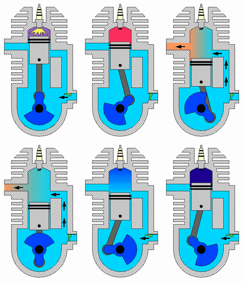
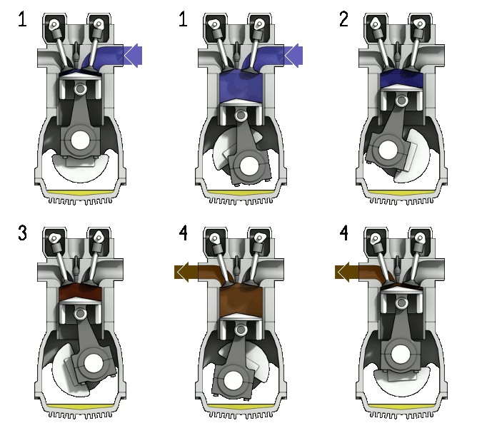
A one cylinder, two stroke engine, is going to have one exhaust pulse per rotation of the crankshaft, so the primary noise from this engine will be first order (1 pulse / 1 RPM). A one cylinder, four stroke motor will have one exhaust pulse every two engine rotations, so the primary order will be 0.5th order (1 pulse / 2 RPM). As the RPMs change, the frequency of these explosions will change with it, but it will always have this physical, mathematical, 0.5th order link to the RPM.
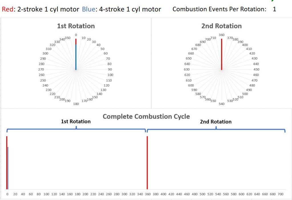
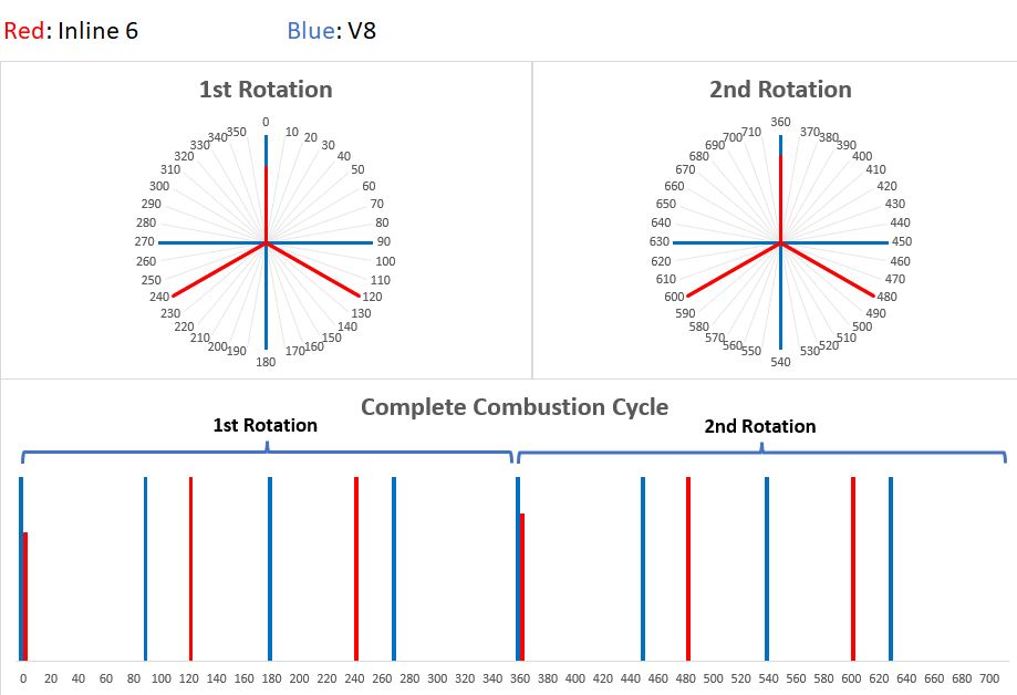
You can see this in the graph below, plotting the ignition events from the spark plug per degree of crank rotation. Each rotation is 360 degrees. The top two plots display that 360 degree rotation as a circle, while the bottom two show the same data on a horizontal axis. The blue “event” is shorter than the red just so you can see both events where they overlap.
Yes, the exhaust sound you hear is the exhaust pulse, not the combustion, but the relative timing is the same for this purpose. The two stroke has one event per RPM, while the four stroke has one every two RPM. The red lines are the 2 stroke pulses, while the blue lines are 4 stroke pulses.
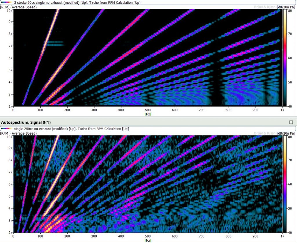
What does this sound look like? I ran the two single cylinder engines with the engine simulator from 2000 – 10,000 RPM. One engine was two-stroke and one four-stroke. Both had no exhaust or headers to eliminate any effects those would have on the resulting sound. In the color map plots below, the two-stroke engine is on top and the four-stroke is on the bottom. You can see that the four-stroke has more lines (or orders) than the two-stroke. These higher order / high frequency lines are called harmonics. Harmonics are integer multiples of the base order. So the base order is 0.5, and the harmonics, or overtones, are 0.5, 1, 1.5, 2, etc. For the two stroke the base order is one and the harmonics are multiples of that (1, 2, 3, 4, 5, etc.).
[Ed Note: I strongly recommend you listen to all the simulation videos like the one below. -DT]
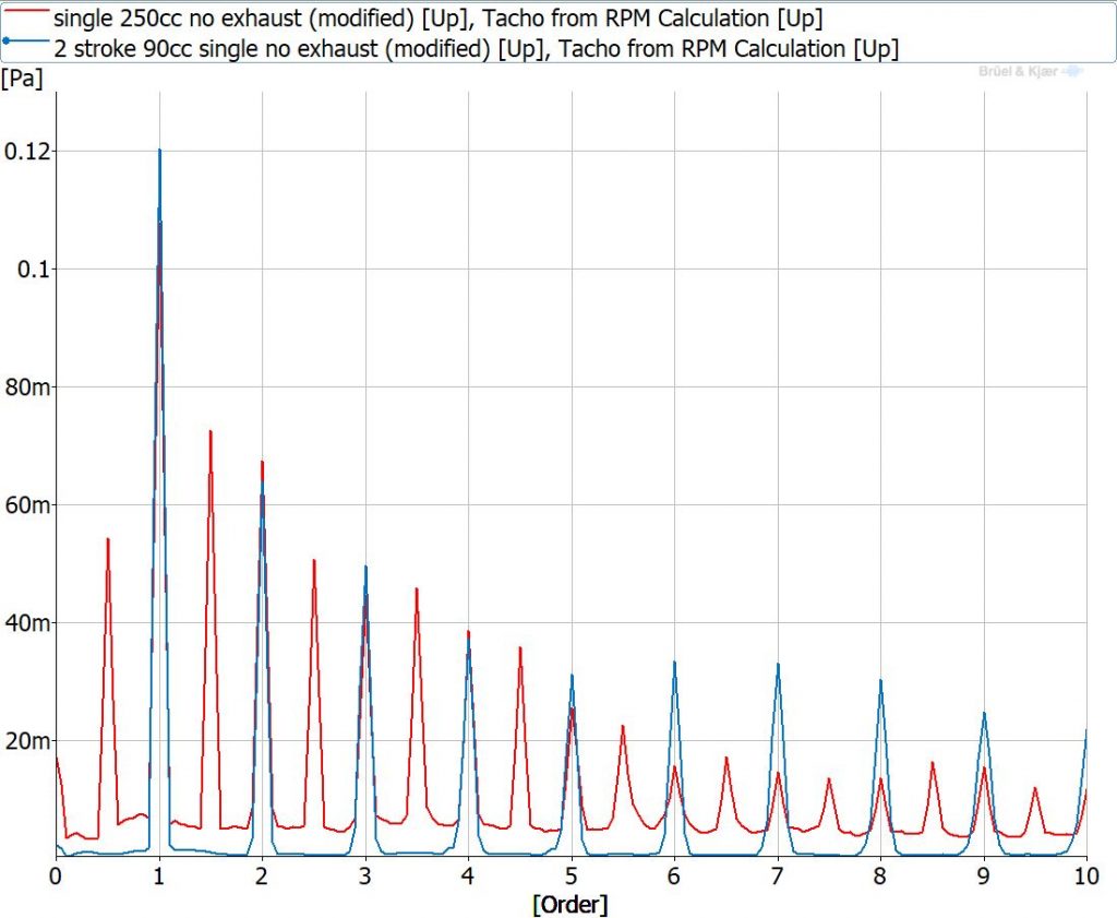
Things get more obvious when we look at the order spectrum. The blue trace below is the two-stroke while the red trace is the four-stroke. The first peak for the four stroke is at 0.5 order with harmonic peaks at every 0.5 order above that. The first peak for the two stroke is at first order with harmonics every 1 order above that.
From this point on, all the engines we will look at are four stroke.
You may have noticed that these single cylinder engines don’t sound great, almost like a vintage square wave synth. The reason for that are the harmonics, which really give each engine type its unique character. We will get into that shortly, but first let’s add more cylinders.
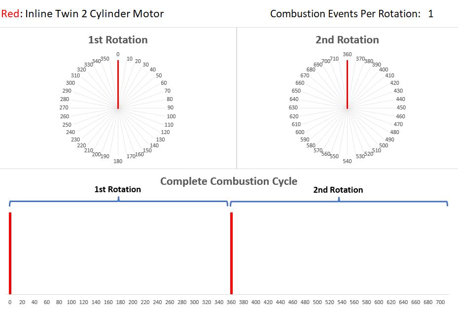
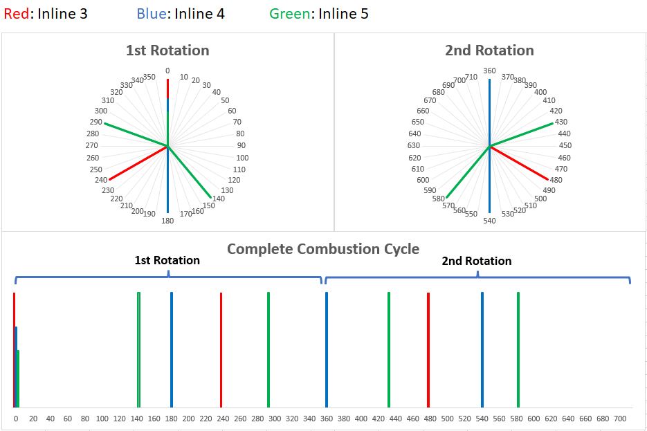
Our next engine is an inline twin or two cylinder. I chose an inline twin instead of a flat or V-twin because those often have an uneven (or odd) firing interval. This means the exhaust pulses of the two cylinders aren’t evenly spaced with each other in the two-rotation (720 degree) four-stroke cycle. Instead of BANG – 0 – BANG – 0, it might be BANG – BANG – 0 – 0. This uneven firing interval gives bikes like Harleys their signature sound. However, when the pulses aren’t evenly spaced things get funky with the orders. I will cover odd firing engines in a later article.
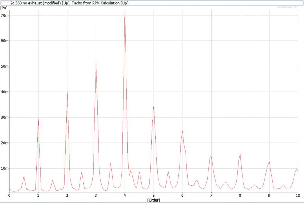
The graph below shows this firing interval for the inline twin. As you see, it has one event per rotation since we have two cylinders, which means its root tone is 1st order with harmonics every order above that. This is shown in the order plot below, with peaks at 1, 2, 3, 4, 5, etc.
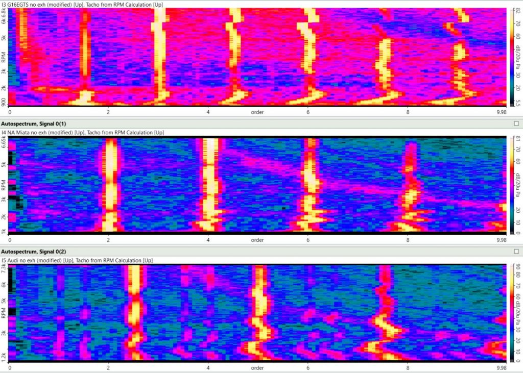
Our next engine is the inline three (G16EGTS Toyota engine). Since there are three combustion events in the two rotation 720 degree engine cycle, it fires every 240 degree rotation of the crankshaft (720/3=240). This results in a 1.5th order root tone, with the next harmonics at 3, 4.5, and 6 shown as a red trace in the order plot below. After that is the inline four (1.8L BP-ZE Miata engine), which has 2 combustion events per rotation, and a 2nd order root tone with harmonics at 4, 6, and 8 shown in blue. Then the inline 5 (2.5L Audi engine) with the 2.5th order tone with harmonics at 5 and 7.5 shown in green. Are you starting to see a pattern here? The root tone is half the cylinder count in a four stroke engine, and the harmonics are multiples of that root tone.
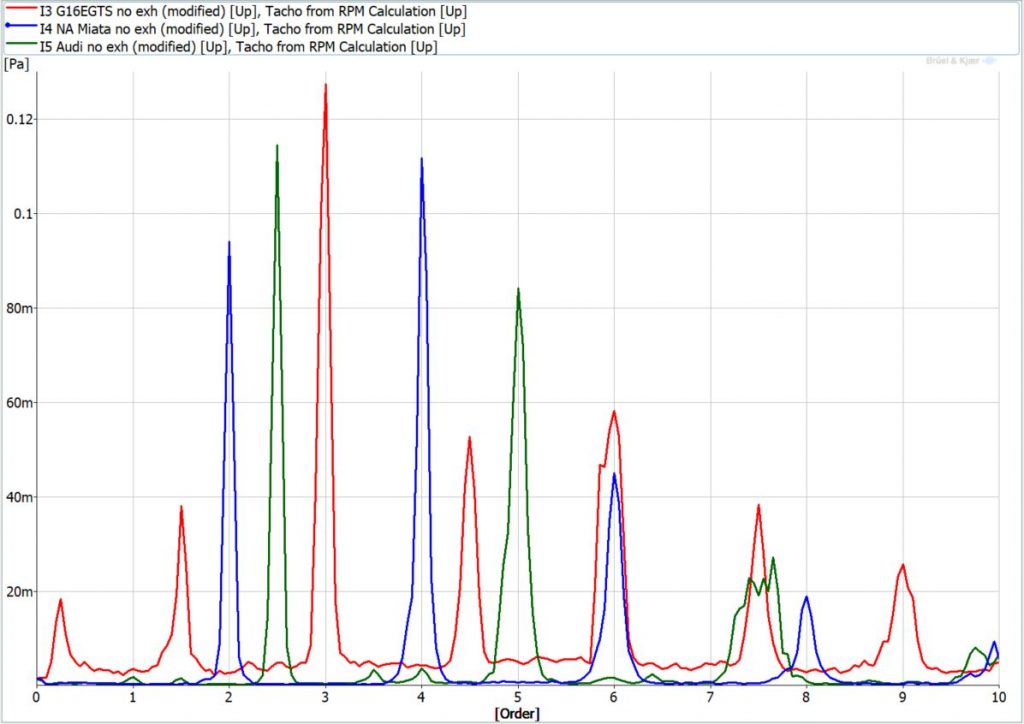
You can see this in the engine runups in the color maps below. The top plot is the I3, middle is I4, and the bottom is the Inline-5. The root order for a four stroke engine is half its cylinder count (a single-cylinder is 0.5, a twin is 1, a four-cylinder is 2), while the harmonics are multiples of that root order. Try to ignore the waviness of the lines. The simulation doesn’t output an RPM channel so I had to generate my own with the analysis software. It’s not perfect, hence the waviness, but good enough for this comparison. When we do real measurements in the field we always find a way to measure RPM directly.
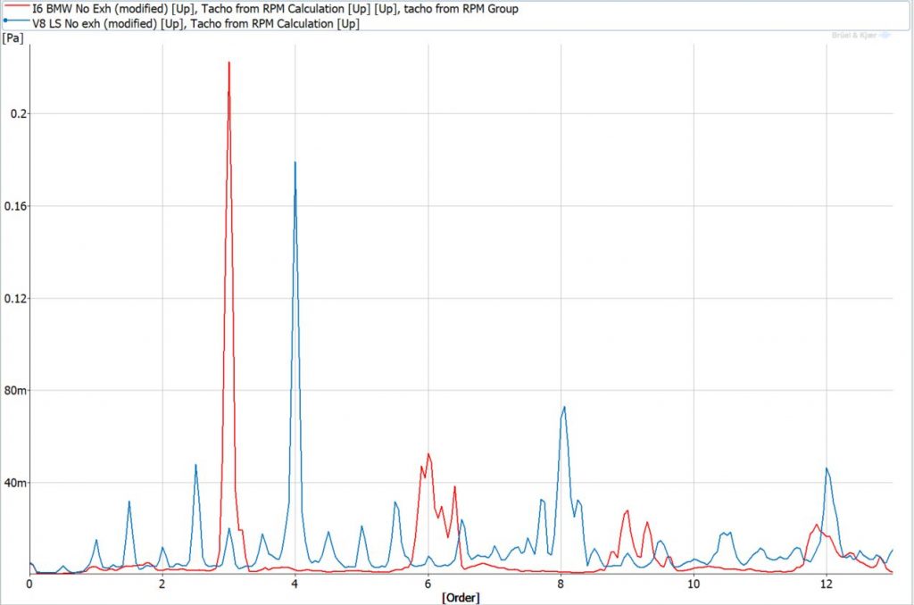
Continuing along we have the venerable BMW M52B28 inline six vs the legendary GM LS V8. For the I6, an exhaust pulse occurs every 120 degrees of engine rotation, or 3 pulses per RPM. For the V8 there is an exhaust pulse every 90 degrees, or four per engine rotation. The primary order for the I6 is third order, with harmonics at 6 and 9. Translated into frequency, at 600 RPM idle, the main frequencies would be at 30, 60, and 90 Hz. At 6000 RPM they would be 300, 600, and 900 Hz. The V8 has 4th, 8th, and 12th order, which translates to 40, 80, and 120 Hz at 600 RPM idle, and 400, 800, and 1200 Hz at 6000 RPM. Remember this combination of frequencies is the musical “chord” that creates the engine sound.
Cylinder Layouts
“What about different engine types?” you may be asking. “You’re showing us a bunch of inline engines and then throwing a Vee in there. Don’t Vee engines and flat/boxer engines and inline engines have their own distinctive sound?” Not exactly.
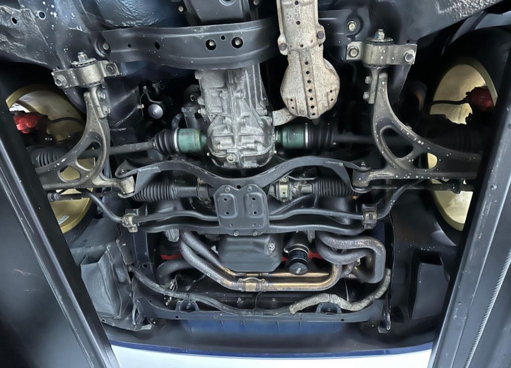
If you put a V6, an inline 6 and a flat 6 on a dyno with no headers they will basically sound the same. As long as those exhaust pulses are coming out of the heads at the same frequency, and those pulses are taking the same path to your ears, you won’t be able to tell them apart. However, in the real world, the exhaust pulses from each cylinder aren’t taking the same path to your ear — they have to go through a manifold and then through the exhaust. Due to cost and packaging constraints, different engine configurations have certain exhaust manifold styles, which have a huge effect on the resulting sound. (A Vee, for example, has two manifolds instead of just the one that an inline engine has).
The distinctive Subaru burble, for example, happens because the turbo is usually mounted on the passenger side of the engine. The exhaust pulses from the driver’s side cylinders have to travel farther to get to the turbo than the pulses on the passenger side — it’s an unequal length manifold. Since they have to travel a longer distance, it takes more time, and the pulses are no longer hitting your ears at evenly spaced intervals, which affects the frequencies you hear at the tailpipe. There are many tales on the interwebs of Subaru drivers installing equal length headers for more performance, only to be disappointed that their burbly Subaru now sounds like a regular inline four.
We can see this in the simulation. The plots below compare a 3.5L Toyota 2GR-FE V6 (red trace) with a 2.8L BMW M52B28 I6 (green trace) and a 3.0 EZ30 Subaru flat 6 (blue trace), with and without an exhaust. The first order plot is with no exhaust system, and the primary frequencies the engines are making are the same, at 3rd, 6th, and 9th order. There is a spike at 1.5th order for the Toyota V6, but if you look at the color maps, this frequency doesn’t appear until over 5000 RPM where a VTEC style system kicks in, creating some half order noise. Below this RPM they look almost the same.
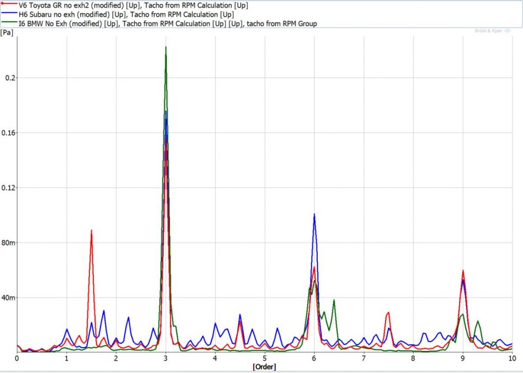

FFT Plot – Six Cylinder Comparison No Exhaust – V6 (top) vs Flat 6 (middle) vs Inline 6 (bottom)
You can see in the colormaps above, the frequencies of these different six cylinders line up with each other.
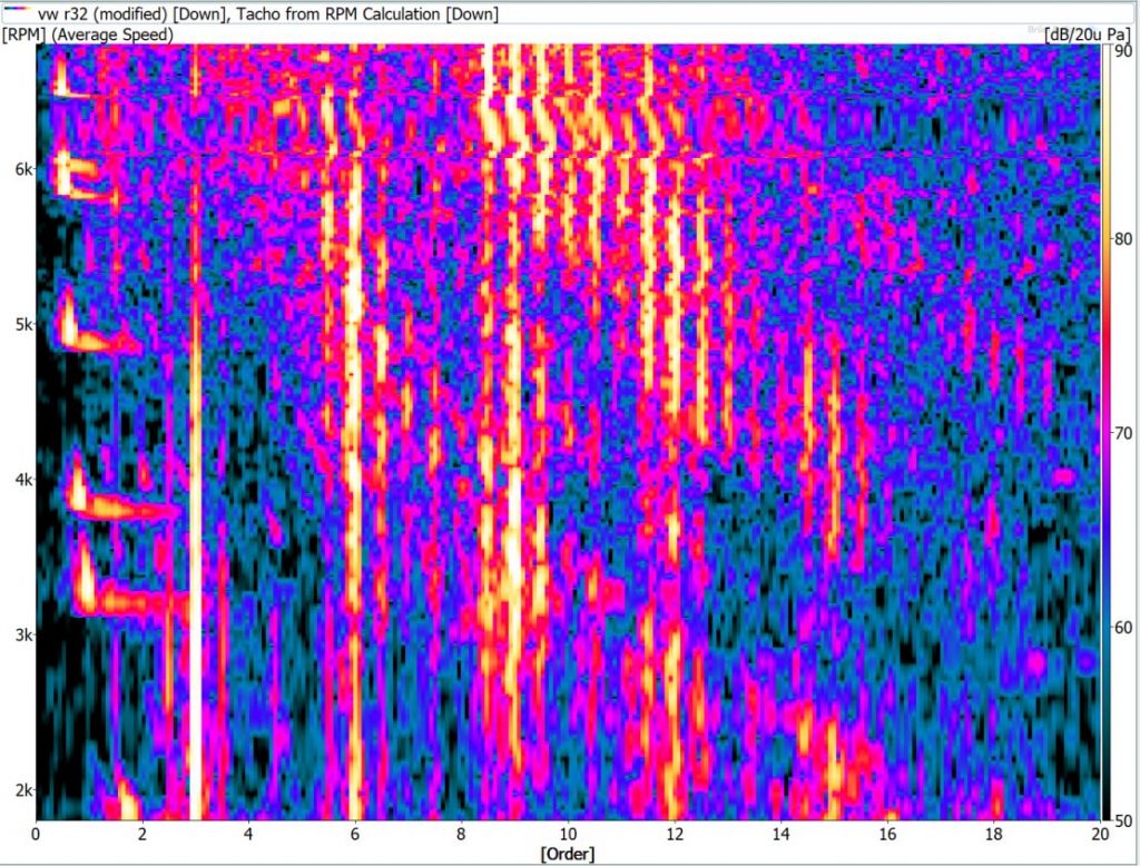
With a few keystrokes I re-installed the exhaust systems in the simulator files, and the graphs look much different. The signature six cylinder frequencies are still present at 3, 6, and 9th order, but there are a lot more harmonics showing up all over the place. You can see the V6 has spikes at almost every half order from first to tenth order. The flat 6 Subaru (which is non-turbo so doesn’t have the super unequal length exhaust) has peaks in order-multiples of 1.5, with the strongest peaks at the firing frequency harmonics. The BMW I6 is mainly the firing frequencies with sidebands at 2.5th and 3.5th order. This is even more apparent in the color maps below, showing the unique sound signature of each engine.
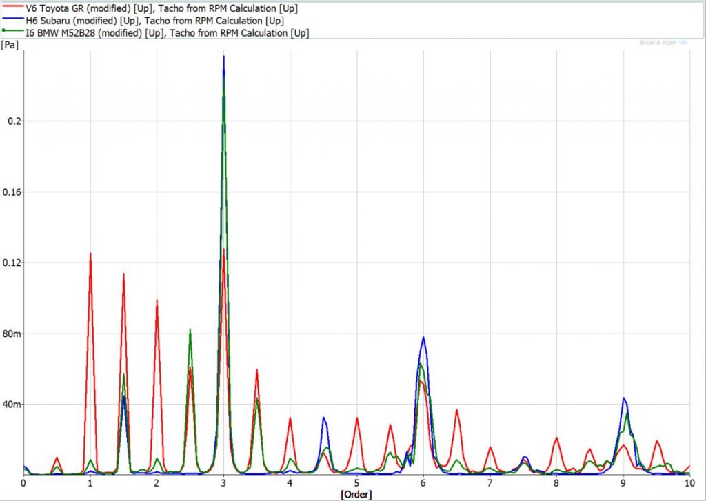
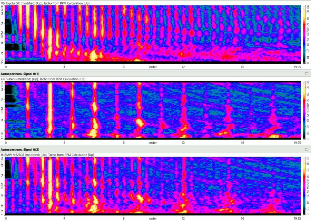
Now we will get into how these extra frequencies are made, and how they affect the sound’s character.
Harmonics
I’m hoping this all is making sense — or at least that some of it is.
“But what’s the deal with all these harmonics?” you may ask in your best Seinfeld voice. “I get that four pulses per revolution in a V8 will make a 4th order noise, but where is the 8th and 12th order noise coming from? There are only four pulses, I don’t see any multiples there!”
This is an excellent point, and gets to a phenomenon that pops up in everything from electrical power systems to music to physics. Pure tones — perfect sine waves that only generate one frequency — are like honest politicians: they don’t exist in the real world. Even tuning forks, the gold standard of making singular tones, have harmonics. They are just much quieter compared to the primary frequency. Any deviation from that perfect sine wave is the result of additional frequencies added to the mix.
Harmonics are everywhere, and they add things like color and timbre to a sound. They’re the reason why you can tell the difference between musical instruments even if they are playing the same note. Check the graph below, showing the same middle A musical note played by a tuning fork, flute, violin, and a singer. The left plots are the pressure waves recorded and the right plots are the resulting frequency spectrums.
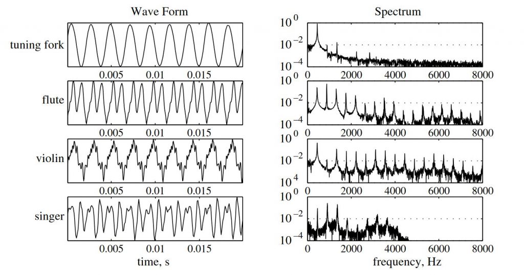
You can see the tuning fork doesn’t make a perfect sine wave but it’s very close, and there are a few tiny harmonics peeking up from the weeds in the spectrum. The wave forms of the other instruments look like they were being drawn by somebody with a live taser in their pocket. The overall wavelength is the same (the spacing between the major peaks and troughs) which is why the 440 Hz peak is the first one in the spectrum, but all the other nooks and crevices in the waveform create the rainbow of harmonics that give each instrument their character.
The world is a messy place when it comes to math and physics. The sound of a violin is created by a taut bow of horsehair being dragged across a steel string, which will vibrate with a number of modes based on the length between the bridge and the player’s finger. The frequencies created by these modes vibrate the neck and the wooden body of the violin, which have their own resonances (a resonance is a frequency that an object naturally vibrates at due to its structural properties) including the resonance of the cavity of air inside the violin body. The construction and tuning of violins has been perfected into an art over hundreds of years, making a distinctive sound that can bring tears to your eyes. That is all due to the harmonics.
This video illustrates how different frequencies add up to create these waves. It’s worth a viewing:
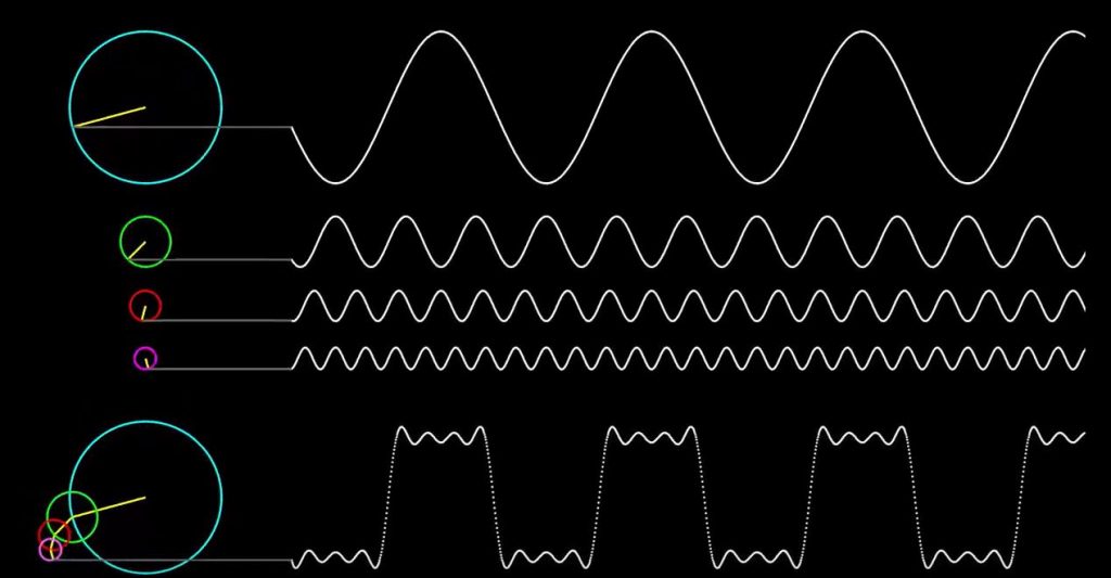
If we look at the pressure pulses in an exhaust in the photo below, we see it’s far from a perfect sine wave, and looks closer to the square wave above. That is because the process is messy. Your exhaust valve or valves open, the piston yeets the exhaust gas through the head, and the valves slam shut. All those little ripples are what create the harmonics above the root tone or frequency (which are always multiples of the engine’s firing frequency (3, 6, 9, 12 etc.)).
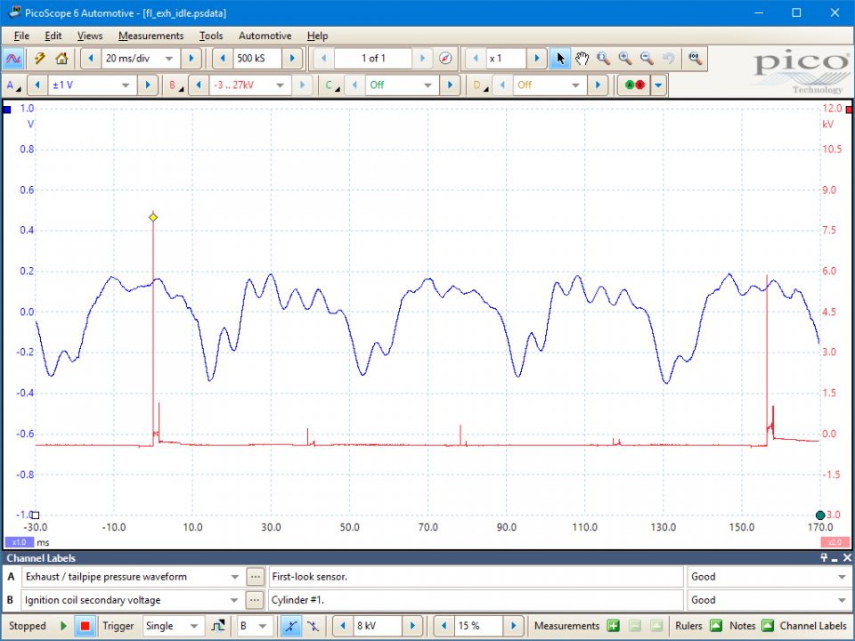
As I mentioned before, when you add headers and an exhaust, those pressure pulses change. Each pulse is taking a different path to your ear through the tubes in your exhaust manifold, and some of those paths are longer than others. As the evenness of the pulses gets scrambled by different header lengths, different harmonics will appear. Then the exhaust and any mufflers will change the sound further. But it all starts with the base set of frequencies — or the chord — that your engine creates.
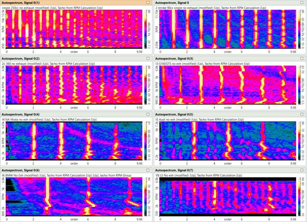
To review, we have all the order spectrums of the engines we’ve looked at in the graph above. As you can see, adding cylinders increases your root note or frequency. The distance between your harmonics also increases. As your RPMs go up, not only do these frequencies increase, but the spacing between them increases as well. These frequency differences create the distinctive chords we all know from our favorite engine. I added a table below summarizing these orders, as well as to show the frequency at 6000 RPM as an example.

It’s Header Time!
Now we will get into headers and the transformative effect they have on the character of an engine’s sound (I’m going to use header and exhaust manifold interchangeably). Header design is a black art and a science. It is all about physics, and you could write a whole book on the subject, but I’ll just be covering some of the basics here. We will start this journey with a metaphor. Imagine you and five of your best friends are at a unique waterpark. All the slides have six inlets, which eventually come together into one tube that dumps you into the pool. You climb the steps to the first slide — which, again, is one of six equal length tubes that swirl around before combining into the main chute. You all jump into your tubes one after the other, and after a wild trip you are funneled into the main tube and into the pool. Since the tubes were all the same length, you all splash into the pool at the same tempo and in the same order as you began your slide.
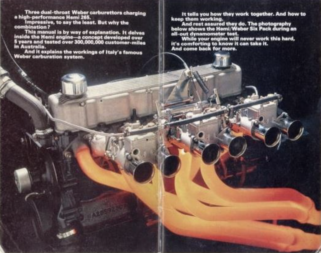
For the second slide, many of the primary tubes have different lengths. You all jump in one after the other again. However, since you are all traveling different distances, your timing gets scrambled. A couple of your friends bump into each-other and become a tangled mass of arms and legs. You all land in the pool at quite a different tempo and order than you jumped in.
The last slide also has unequal length primary tubes but they are much shorter, combine together at random spots, and dump into a larger chamber before continuing down the chute. You all jump into your primary tubes and soon find yourselves colliding and sloshing around the chamber before being funneled into the chute. You all hit the pool in an almost random order compared to how you started your journey.
If you haven’t caught on already, you and your five friends are the exhaust pressure pulses from a 6 cylinder engine, the primary tubes are your headers, the main chute is the exhaust, and the splashes are these pressure pulses hitting your ears. The length and arrangement of these tubes will affect the timing of the pulses out your tailpipe.
While this is a useful metaphor, real life is much more complex. The pressure waves traveling through these tubes are moving through air, which has mass and inertia. Pulses can bunch up into another at a bottleneck, combine with one another, or cancel each other out. Changes in pipe diameter, the shape of their connections, even the pulses hitting the atmosphere at the exhaust tip can reflect these waves back into the exhaust system, further influencing the sound and performance of the engine (exhaust scavenging). With sound, timing is everything. The varying distances traveled for different cylinders and how they interact with each other affects the timing of when they will exit the exhaust pipe and thus the frequencies your ears perceive.
Rolling in My 5-0
A simple way to demonstrate the water slide metaphor above is listening to drastically different header designs on the same engine. Take a look at the Ford 5.0L V8. Ford shares engines across multiple platforms like everyone else. This engine is installed virtually unchanged in the utilitarian Ford F-150 and the legendary Mustang muscle car. Although they both have a distinctive V8 sound, a Mustang at full chat will stir your heart much more than an F-150. A lot of this has to do with the header design.
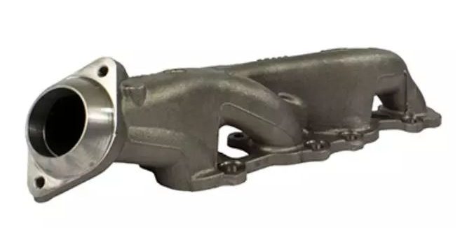
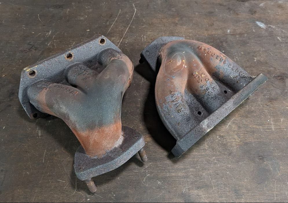
Lets first look at the F150. It’s a cast manifold whose primary design concern was space and cost. There is no apparent effort in tuning the lengths of the primaries; they all just mush together into one tube in as short a distance as possible. You can hear an example of how this sounds here.
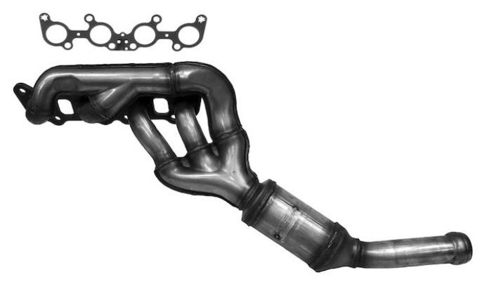
Next we have a stock 5.0L Mustang. This is drastically different than the F-150. It’s constructed from welded, stamped steel tubes. The runners are longer. They are far from equal length, but much more consideration was taken in its design and how the runners meet together before the catalytic converter. You can hear how this sounds here.
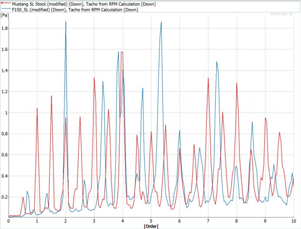
Let’s take a look at the spectrums of these two dyno tests. The Mustang is red, while the F-150 is blue. The fourth order, or root note/frequency, is the same between the two engines. The Mustang has half orders sprinkled evenly across the spectrum. These half orders give the Mustang its burbly, almost Chewbacca like muscle car like sound via a phenomena called frequency beating which I’ll explain below. The F-150 has a strong 2nd order, which gives it its low end grunt, and a bunch of other seemingly random orders. The stubby, cast iron manifold of the F-150 muddies up the sound.
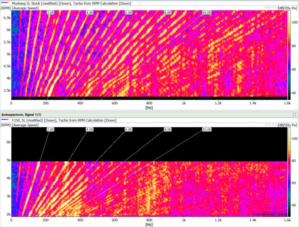
More details are revealed in the FFT plots, with Mustang on top and the F150 on the bottom. You can see the Mustang’s many engine orders increasing high up in the frequency range giving it that high RPM roar. The F-150’s fewer orders stop right at 400 Hz. This is due to the exhaust system cutting out those orders in that frequency range. This is a prime example of different header designs drastically changing an engine’s sound.
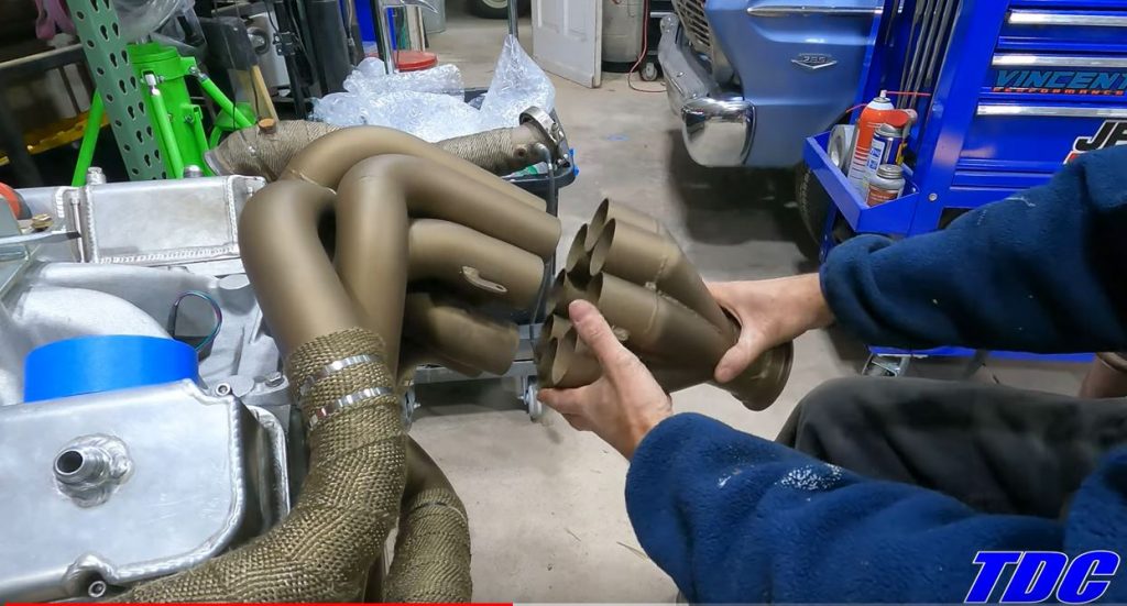
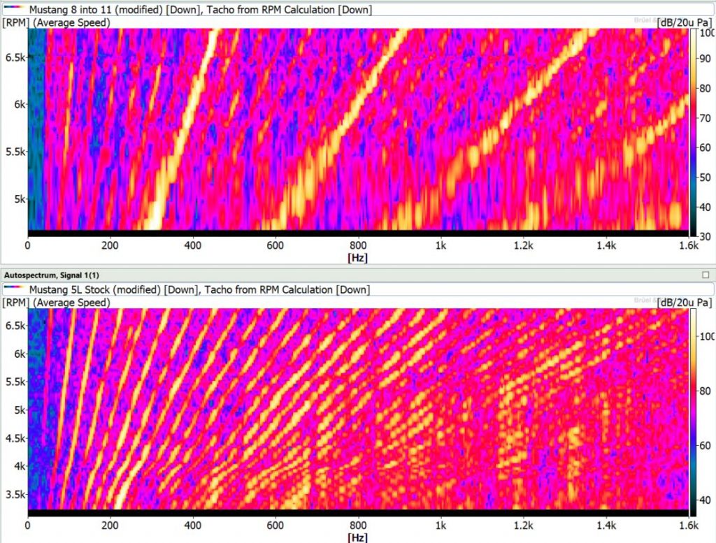
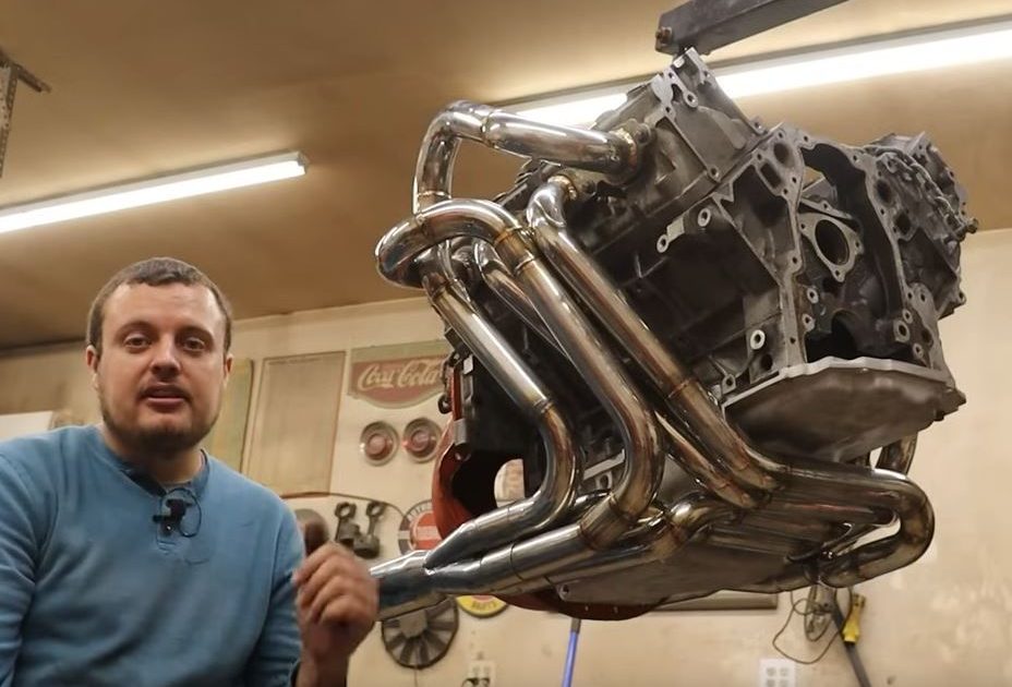
If we really want to prove the point, we can go to an extreme with another Mustang V8. Here is a modified 1965 Mustang with an insane 8 into 1 exhaust with equal length primaries built by Track Day Classics. You can listen to how this once burbly muscle car now sounds like something from F1.
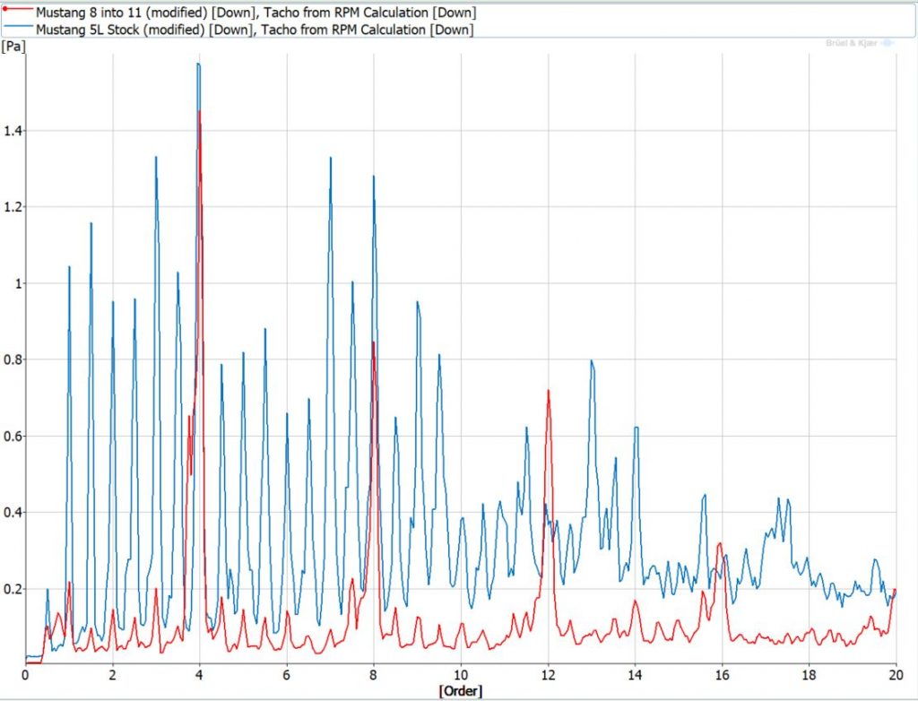
Check out the plots below comparing the equal-length 8 into 1 exhaust (Red) to the stock Mustang GT (Blue). With equal length primaries, the 8-into-1 exhaust pulses can exit the engine unencumbered without interacting with each other. As a result, the engine sound is just made of the firing frequency and their harmonics (4, 8. 12 and 16). This gives it a very distinctive, clean sound reminiscent of an exotic supercar or racecar. Equal length headers are more expensive to design and manufacture, but they are the most efficient way to expel these exhaust gasses. For high powered racecars and exotics, money isn’t really an issue, and efficiency is important as it leads to more power.
This gives exotic cars their distinctive sound. The base “chord” that the engine makes comes through the exhaust cleanly, and hearing the engine wail as it races towards its high redline can give you goosebumps. The sound fits with the character of a precision built, high performance machine. It is why it’s so baffling seeing it coming from a classic muscle car.
The stock Mustang GT in comparison has “all the orders.” Fourth order is the most dominant, but the others aren’t too far below it in terms of sound level. You’ll also notice that 4th order is the lowest order numerically for the 8 into 1 exhaust, meaning it lacks the low frequency sound that the regular Mustang GT has (all the orders between 1 and 3.5). That low end rumble is a beloved characteristic of muscle cars, and losing those orders would make the Mustang GT sound out of place. All those half orders gives the GT a more “rough” and burbly sound compared to the very tonal and sharp sound of the race car. The uneven lengths in the Mustang GT’s primaries scramble the timing of the pulses leaving the exhaust, creating this forest of orders.
Firing Order
Firing order also comes into play here. If you watch the fabrication video for the 8 into 1 header, you’ll immediately notice that its construction is unconventional to say the least. To get that clean, race car sound, American V8 lovers have to employ some high level fabrication skills to create crazy collectors or 180 degree headers like in this excellent explainer video where some primaries are snaked under the oilpan to reach the other side of the engine. Why do some engines, particularly ones in high dollar exotic cars, get that race car sound with more “conventional” header designs, while the “traditional” V8’s look like they’re being attacked by a pile of robot snakes?
The answer, my friends, is firing order. This is the sequence that each cylinder “fires” during its combustion cycle. Check out my diagram below (the colors of the arrows are different just for readability). Many high-powered, exotic engines have flat-plane crankshafts, and the firing sequence always alternates between the left and right bank of cylinders. It goes R L R L R L R L. Most traditional V8 motors have a cross-plane crankshaft, it looks like an X. Looking at the cross-plane engines in the diagram, they have portions of the sequence where two cylinders on the same bank fire one after another (the curved arrows), instead of switching banks each time like a flat-plane crank. Its sequence will go L L R L R R L R. Each bank has two cylinders that pop off one after another, which doesn’t happen with a flat-plane engine.

[Ed Note: Engines cylinders are numbered in a specific way; Ford numbers theirs differently than GM, with the former’s V8s being 1,2,3,4 on one side, and 5,6,7,8, on the other, while GM alternates side-to-side. A straight six engine is pretty much always counted 1-6 starting front to back, with the firing order being 1,5,3,6,2,4.
I’d also like to mention here the Buick “odd-fire” V6 put in Jeeps in the 1960s. This was basically a v8 with two cylinders lopped off in that it had a 90-degree vee-angle, but the crankshaft had 120-degree offset journals, meaning a combustion event didn’t happen every 120 degrees like it would on an “even-fire” V6, it happened at 90 degrees then 150 degrees, then 90, then 150, etc. — odd-firing! The video above explains it, and thus explains why the odd-fire V6 has such an interesting burble. -DT].
I’m not going to get into all the advantages and drawbacks of flat vs cross-plane engines, this article is long enough. But sound is a key difference. Remember, these extra harmonics come about from changes in the timing of the exhaust pulses and their interaction with each other. Even if you have equal length headers on each side of a cross-plane engine, if you look at the collectors, the pulses aren’t going through at an even rate. During the engine cycle you’ll have two pulses one after another, and a long pause while the other bank fires its two subsequent cylinders. The pulses from the flat-plane engine on the other hand are even and steady. You have Bang – 0 – Bang – 0 – Bang – 0 at either collector in a flat-plane engine instead of Bang – Bang – 0 – Bang – 0 – 0 – Bang – 0. This uneven sequence gives you the lovely rumble that most V8s are known for. Having adjacent firing events on the same cylinder also gives more opportunity for the pulses to interact with each other when you have unequal length headers, as most of these cars do.
To get that pure tonal F1 car sound out of a cross-plane V8 you have to hire one of those fabrication wizards like the guys above and hope you have lots of room in your engine bay (and your wallet) to create a monster set of headers that route these uneven pressure pulses so they are even on each side. Not a small task.
Did It All For The Wookie
I’m sure some of you saw that Star Wars reference I made earlier and were waiting for this moment. We can’t mention Chewbacca without taking a look at a beloved engine that has one of the most distinctive sounds of the modern era, Volkswagen’s VR6. If you aren’t familiar with the VR6, it’s a V6 with a very narrow cylinder bank angle, between 10 and 14 degrees, compared to the 45 to 90 degree angle of a traditional V6. This compact design allowed VW to squeeze six cylinders in roughly a four cylinder space. Since both banks share a common head, the exhaust ports are all on one side. The exhaust manifolds aren’t exactly equal length but are fairly close. This means the difference in distance that the pulses travel between the two cylinder banks is much less compared to a transversely mounted V6 whose front pulses can travel several feet further to get around the engine than the rear pulses. This combined with the engine’s unique firing order give the VR6 a lovely growl due to an acoustic phenomena called beating. You can hear a 2004 VW R32 with the VR6 engine on the dyno here.
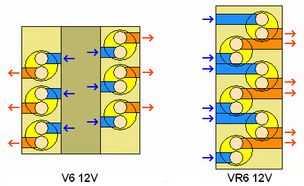
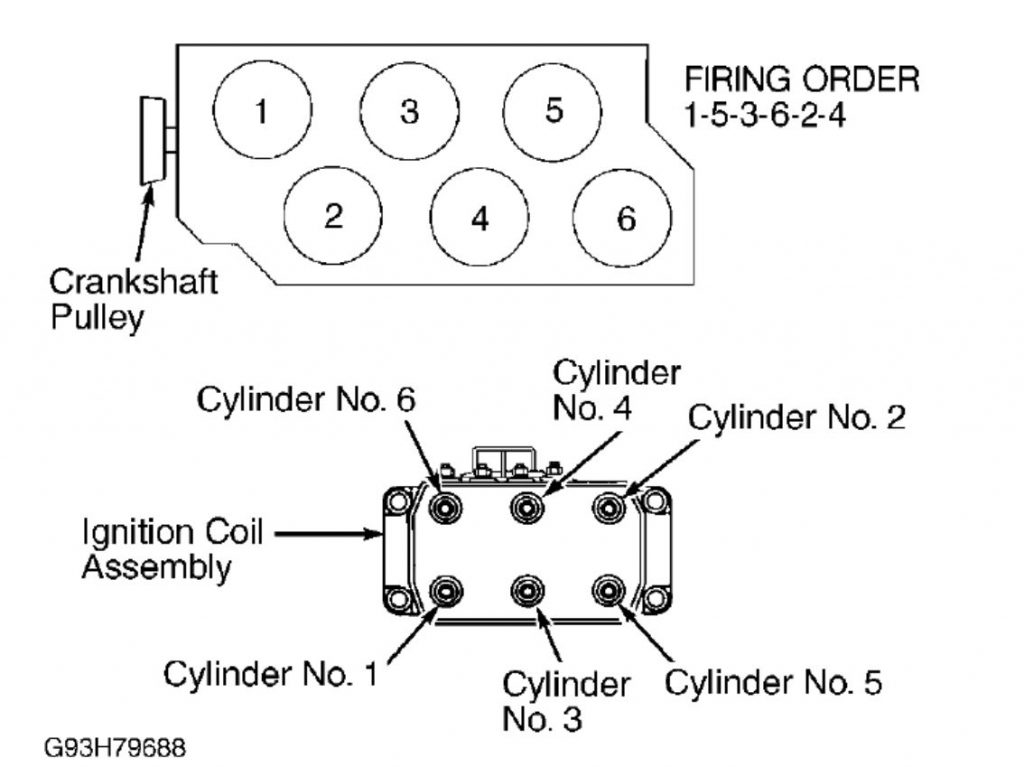
As you can see below, the first three cylinders to fire are the ones closest to the manifold, followed by the farther three on the front (the left side of the drawing) of the engine. So you have three close, three far, three close, three far. The exhaust pulses for the three far cylinders have to travel several more inches than the close cylinders, so they are slightly delayed. If you look at the manifolds, the branches are close in length, with an inch or so difference, but the different lengths are evenly distributed among the banks. Cylinder one and cylinder four each get a longer branch, two and five get the mid size, and three and six get the shorter one. So the slightly differing primary lengths aren’t favoring one bank over another. The distance the front bank’s pulses have to travel to go over the rear cylinders and out the back of the cylinder head is the most important factor to the VR6’s sweet, sweet burble. Here’s why.
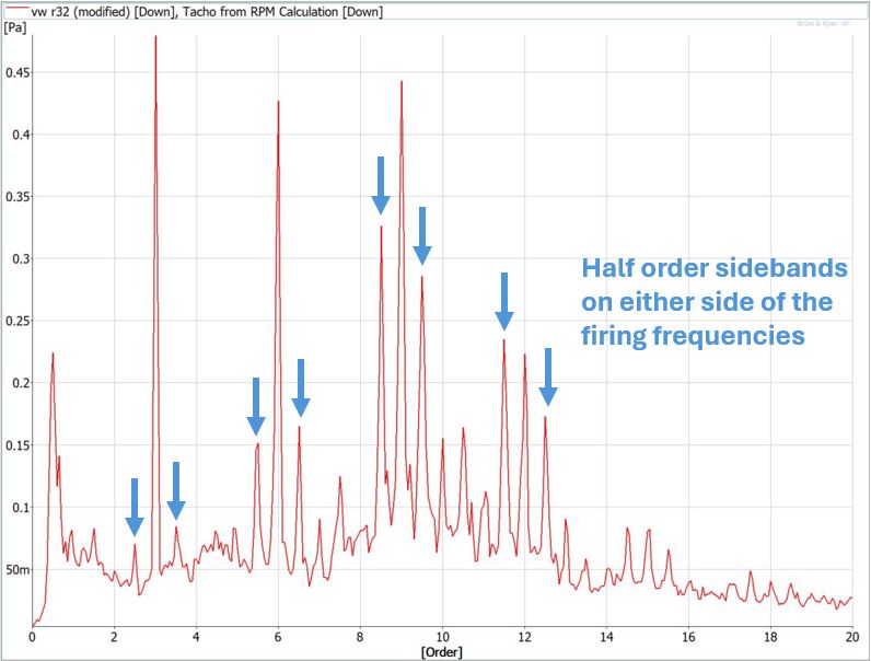
This modulation between the three far and three close pulses creates something called sidebands. If you look at the firing related orders (3, 6, 9, 12) you will see there are also orders plus and minus 1/2 order on either side of each of these firing orders. So 6th order is surrounded by the 5.5 and 6.5 order, 9th order is surrounded by 8.5 and 9.5 order and so on. We see sidebands a lot in gear testing. If a ring gear in an axle is slightly oval in shape, it’s not going to spin at a constant speed. It will have to slow down slightly on the pointier sides and speed up slightly on the flatter sides. Think of it like a football rolling end over end, the rate that it rotates about its central axis will vary quite a bit compared to a soccer ball which rotates smoothly. This steady variation in speed will create a steady variation in frequency. It will go up, down, up, down slightly with every rotation.
So if you look at a frequency plot, instead of just having a single peak at the gear mesh frequency, you’ll also get one at a slightly lower frequency for the slower parts of its rotation, and one at a higher frequency for the faster rotation. Remember, frequency is events (waves, pulses, gear meshes) per second, so when it’s going faster you’re getting more, and when it’s going slower you’re getting less. A similar thing happens when the second three of the VR6’s exhaust pulses are delayed compared to the first three. It helps that the cylinders within each bank are delayed by a roughly equal amount due to the header design. The closely spaced frequencies in the VR6 engine sound cause the acoustic phenomena I mentioned earlier: “beating”.
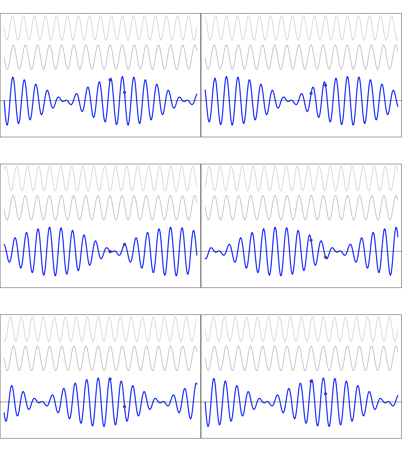
“Where’s this beating you keep talking about?” you ask nervously. Fear not my friend. Beating is an acoustic phenomena that occurs when you have two or more frequencies that are very close to each-other. You get a mix of constructive and destructive interference which results in what’s called amplitude modulation, ie. the volume going up and down at a regular rate. You can read a more detailed explanation of interference in my Active Noise Control article, but the graph below explains it pretty well. The two grey waves are frequencies that are very close to each other, but not the same, while the blue wave is what you get when the grey waves are combined. When the peak of a wave and the trough of a wave add together, they cancel out. When two peaks add together, their energies combine. The taller the wave is, the louder it is. When these tones are close in frequency, these peak and trough combinations phase in and out of each other. Instead of hearing two distinct tones, you hear one whose volume goes up and down at a regular rate.
I think it’s important to hear this in action so check out this video below. As you’ll see in the video, the rate of the volume modulation is the difference between the two frequencies. So if you have one frequency at 500 Hz and one at 510 Hz, the volume will go up and down ten times per second (510 – 500 = 10), called the beat frequency. As these frequencies get further apart, the rate of volume modulation increases, until you get to the point where the modulation becomes imperceptible and you just hear two discrete frequencies.
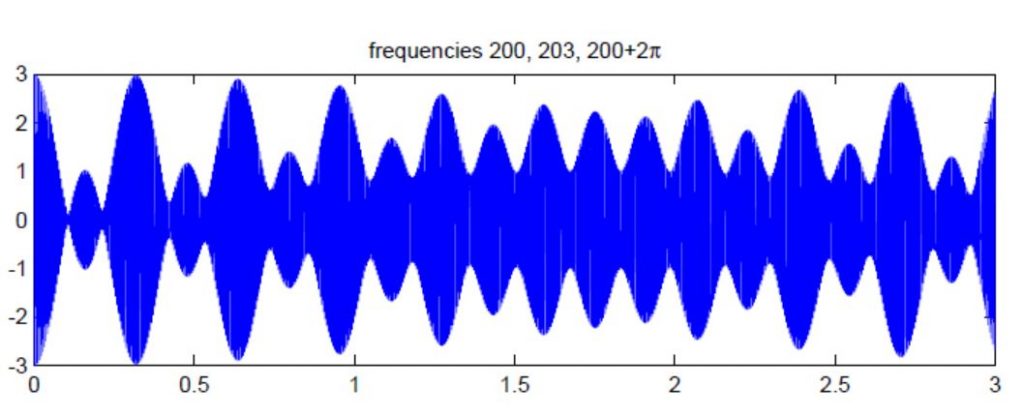
How does this relate to the sideband frequencies in the R32 spectrum? The distance between the side-bands and firing frequencies is between 30 and 40 Hz, so the volume is going up and down about 30-40 times per second. This modulation is quite fast but still detectable and at the point where you can discern the separate frequencies. However, with the VR6 we have three frequencies combining instead of two which adds another level of complexity (the firing order and its two sidebands). You have three sets of peaks and troughs adding and subtracting from each other at different rates, creating multiple rates of modulation happening at the same time (as you can see in an example graph below). This gives the VR6 that signature Chewbacca growl.
Check out this link where I set up a tone generator with three frequencies. These correspond to the VR6’s 6th order and its side-bands at 5.5 and 6.5 order when the engine is at 5000 RPM. Turn on the top and bottom ones first and it sounds like two tones. Then turn on the middle one and you’ll hear the modulation going crazy. It’s fun moving these frequencies around and hearing the modulation undulate in different ways, at least until your co-workers literally beat you up.

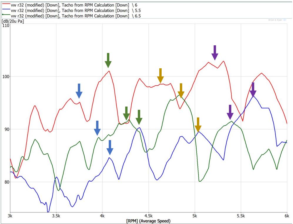
You can see this in the data from the R32 run-up. The graph below shows the order slices for 5.5, 6, and 6.5 order (literally slicing them out of the colormap above, so its dB vs. RPM). The 6th order (red trace) is obviously the loudest, but you can see it dipping at regular intervals. When its loudness goes down, the 6.5th order (green trace) goes up, and when that starts dipping the 5.5th order (blue trace) starts increasing and the process repeats. So you end up with a series of repeating cascading peaks where the three orders are warbling between each other as the engine increases in RPM. This warble is the Chewbacca noise we all love.
A similar thing happens to the orders during the Mustang GT’s runup, as its spectrum is full of half orders, giving it a burbly roar. This beating phenomena is pretty common, giving many vehicles a rougher, growly sound. What makes the VR6’s sound so distinctive? Its unique design has an asymmetric symmetry if that makes sense. You have a very tonal noise with strong firing orders (3, 6, 9, and 12) almost like a six cylinder with an equal length manifold. But the equal delay of the second three pulses in the engine cycle creates the sidebands just around the firing orders, instead of through the whole spectrum like the Mustang GT. This mix of strong tones that are modulating in volume and frequency gives the VR6 its beloved Chewbacca moniker.
Like Physics, the 3800 is Eternal
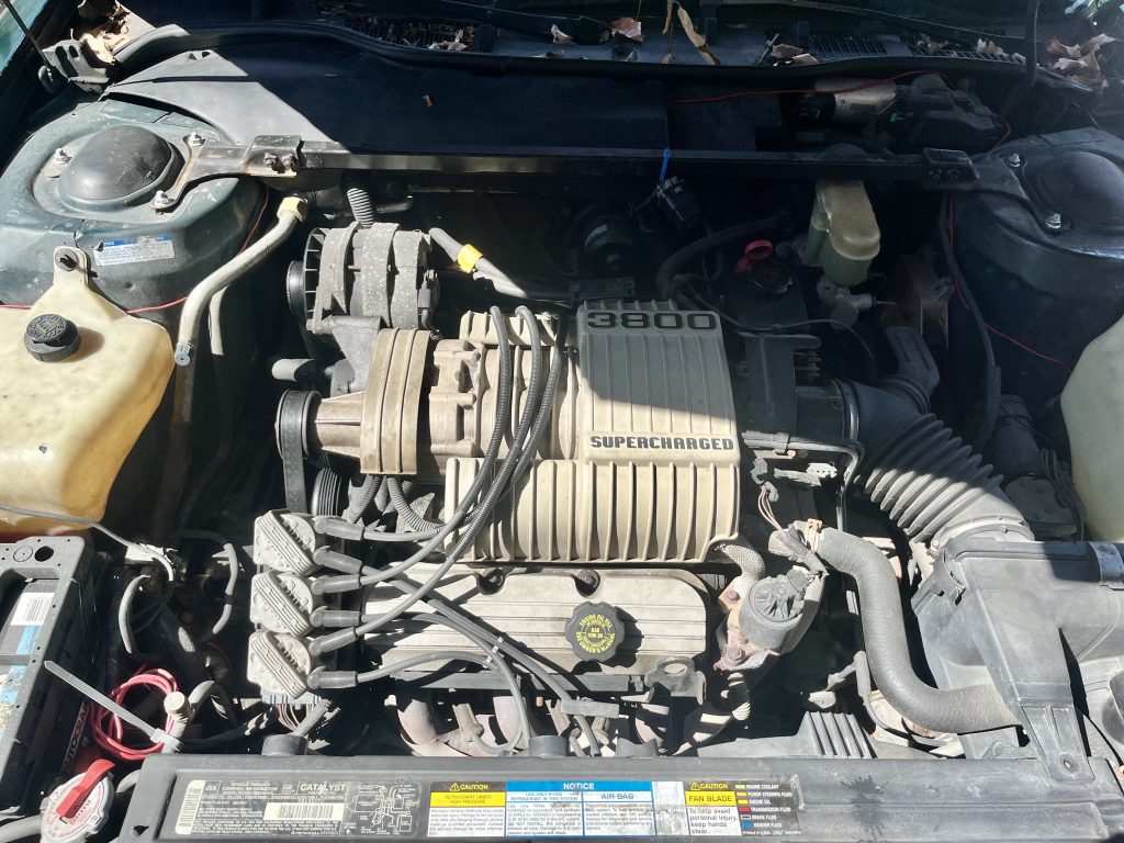
For comparison we can look at a V6 that I have in my stable that has a reputation for not sounding great, the legendary GM 3800! As you can see in the photo below the exhaust pulses from the front bank have to go around the engine, over the transmission to the back where they meet up with the rear cylinders and dump into the exhaust pipe. Their journey is about three feet longer than the rear cylinders. I broke out the measuring tape to see how long the pressure pulses have to travel from each exhaust port before they meet the common pipe right before the catalytic converter.
We want to see how the varying path lengths will affect the timing of each pulse. I pulled up my trusty Excel spreadsheet and made the table below. The cylinder numbers are based on firing order. Piston 1 is front passenger side, 2 is rear passenger side, 3 is middle front, 4 is middle rear and so on. The distances are from the exhaust port to where the pipes converge at the catalytic converter. These pulses travel about 1500 feet per second, which I used to calculate the duration of that pulses trip through each primary. I then calculate that delay in terms of crank angle at 600 and 6000 RPM. To create a common starting point and make the graph easier to visualize, I normalized these delays to cylinder 1’s pulse. Think of it like you are sitting at the exhaust collector and start your stopwatch when the pulse for cylinder one blows by.

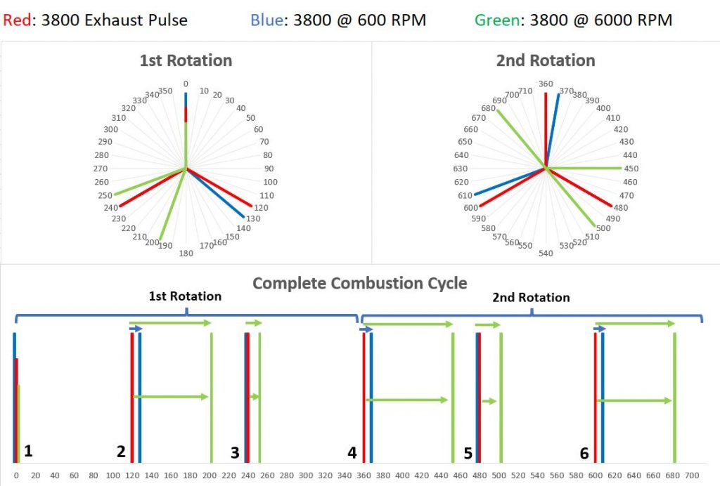
I plugged this data into my engine cycle diagram. The red lines are the timing of the exhaust pulses exiting the heads, and what you’d see at the collector if someone wanted to waste a pile of money and tubing to install an equal length header on a 3800 (next epic SEMA build?). Basically steady pulses every 120 degrees. The blue lines are with the stock headers. At idle (600 RPM, blue lines) every other pulse is delayed slightly, this is because the engine switches cylinder banks every combustion event, and the front cylinder bank has to travel much further to the collector. At 6000 RPM (green lines) these delays are much more pronounced, because while the speed of the pulses remains the same, the engine is rotating ten times faster. Instead of a steady Bang – 0 – Bang – 0 – Bang – 0 – Bang – 0 you have; Bang Bang – 0 – 0 – 0 – Bang Bang – 0 – 0 – 0. We can see how header primary lengths change the timing of the exhaust pulses, and how this timing is also affected by RPM. This is one reason the song or musical chord of your engine evolves in its journey to redline.
As an aside, another example of this is how exhaust scavenging only works in a particular RPM range. This is where the primary tube lengths are tuned so that when a pressure wave is reflected back towards the engine at the exhaust collector, the low pressure portion of the wave hits one of the cylinders when the exhaust valve opens. This low pressure acts like a vacuum, helping to suck the exhaust out of the cylinder and draw in some intake air if there is overlap between the intake and exhaust valves opening. Scavenging only works when the timing of the waves is right, which is why different header designs create peak power over specific RPM ranges.
To see the effect of these wildly spaced headers I analyzed a dyno run of a 3800 engine. Looking at the first plot, 6th order is very strong but third and ninth orders, characteristic orders for six cylinder engines, are very low. 1.5th order is fairly high, which gives the engine its deep rumble. It also has widely placed sidebands at 4.5 and 7.5 order (+/- 1.5 orders around 6th order). Basically the chord that this engine makes is unusual when compared to other six cylinder engines. The compromises in header design are more pronounced in a transversely mounted V6 compared to a longitudinally mounted V6 or an inline six. In the FFT spectrum, I extended the frequency range out so you can see the supercharger whine, the lone order on the left half of the plot.
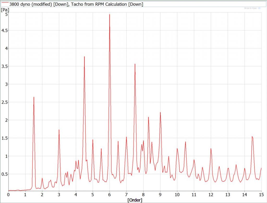
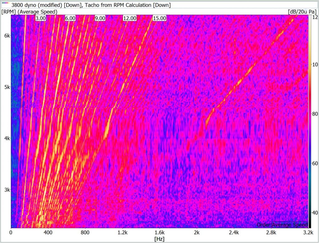
So to review: exhaust manifolds route the exhaust pulses from the head to the rest of the exhaust. The path these pulses take and how they interact will change the frequencies you hear out the exhaust. The more drastic the differences in relative distance that the pulses have to travel, the further the resulting sound will stray from the pure set of tones your engine makes. Sometimes this is good, like in the Mustang GT, which uses unequal length manifolds to create a ton of half orders which gives us that classic V8 growl. Other times, like with the 3800, it gives us something less desirable. In the end, header design is both an art and a science that takes a musical ear to create the sounds we love.
Exhausted Yet?
Thanks to all who’ve made it this far, we still have a few topics to cover. First is your exhaust. After exiting the headers, these pressure pulses pass through an exhaust system before reaching your ears. Mufflers are a critical component and do what their name says, muffle the sound. Now, we all love the idea of straight pipe exhausts, in theory. But in practice it leads to angry neighbors and your own sanity rattling apart as your brain gets constantly blasted by violently loud pressure waves. If we didn’t have mufflers, automakers would fail their standardized noise testing and society would devolve into a Lord of the Flies style hellscape as no-one could get any sleep.
The mufflers in your exhaust can reduce the overall volume, or can eliminate certain frequency bands, or both depending on the design.
There are two main strategies mufflers use to reduce noise: reactive and dissipative.
Dissipative mufflers turn the energy of sound waves into heat via noise absorbing material like fiberglass. The exhaust pulses flow through a perforated tube (which itself helps reduce energy) which is surrounded by the material. These are commonly called “straight through” or “turbo” mufflers, depending on the shape of the tube that the sound travels through the muffler. The path of straight through mufflers is obvious enough, think the classic “Cherry Bomb” style muffler. In turbo mufflers, the exhaust goes on an “S” shaped path through the muffler. The advantage of the turbo muffler is more sound deadening material can be packed into a larger muffler case.

These work best on high frequency noise. How low you can go is based on the thickness of the material; basically it needs to be 1/4 of the frequency’s wavelength or larger to have any effect. This makes sense if you think of the mechanics of how the material absorbs energy. The high and low pressure zones of the sound wave are pushing and pulling the fibers of the material back and forth, converting the energy into heat via friction. High frequency noise has a shorter wavelength, so your slab of fiberglass will have multiple high and low pressure zones flowing through it where the fibers are being pulled apart and squished together.
When you get to the point where the wavelength is four times the thickness of your material, your pressure gradient is limited to atmospheric pressure on one side and the peak high/low pressure on the other side, as you can see in the illustration below. Once your wavelength gets longer than that (ie. your frequency gets lower), the pressure gradient through the material is less and less until you get to the point where you aren’t stretching or squishing the material at all.

To use some real numbers, the wavelength of n 1000 Hz noise is about 13.5 inches, so you need a bit over 3 inches of material to have an effect at that frequency and above. As you’ve seen, most of our engine tones are below 1000 Hz. So unless you have a turbo style muffler with the space to pack some thick layers of material, these mufflers will mostly help reduce harsher high frequency sounds. This is why the cherry bomb style mufflers are preferred by hotrodders who want their engine to sound good but don’t really care how loud it is. The straight-through design also restricts flow the least, which helps with making power.
To reduce the level of your engine’s lower frequency tones you need another strategy.
Reactive mufflers use destructive interference to cancel out specific tones. As anyone who has deleted their mufflers can attest, the awesome sound often comes with an irritating drone at cruising speeds. My Audi S8 has no rear muffler and gets quite boomy at 45 mph. NVH engineers know what frequencies the dominant engine orders are during normal driving speeds, and target them with reactive mufflers.
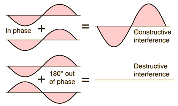
These mufflers use a series of baffles, chambers, and tubes that are designed to create a collision between the high pressure peak of the target frequency’s wave with a low pressure peak and vice versa. As you can see above this will cancel the frequency out. One example is a quarter-wave resonator. This is a simple tube with a closed end whose length is a quarter of the wavelength of the frequency you are targeting. The wave bounces off the back of the tube, and when it returns to the entrance, the phase is 180 degrees out, which eliminates that frequency.
Helmholtz resonators are similar but different. They use chambers attached to the exhaust path via a smaller tube or “neck”. The air in the chamber acts like a tuned mass damper, resonating at a specific frequency based on the volume. This pushes and pulls the column of air in the neck tube which cancels the frequency with destructive interference. It’s like the tone you hear when blowing across the opening of a bottle.

So that is the gist of exhaust systems. After the headers you have this full spectrum of noise, some of it good, some of it bad. Your exhaust system uses a combination of dissipative and reactive strategies to quiet down specific chunks of that spectrum so your vehicle sounds great and is legal to sell. A luxury car will have a bunch of huge mufflers to basically eliminate exhaust noise, while a sports car can get away with fewer, more carefully tuned mufflers.
As a funny aside, during a vehicle’s development, NVH engineers sometimes need to totally eliminate a vehicle’s exhaust sound. We will measure the car normally, then again without the exhaust noise to find its contribution to the total vehicle’s sound. Since we don’t have time to engineer and build a fully tuned exhaust we use what is called a BAM, which is an acronym for Big Ass Muffler. It basically looks like a cherry bomb muffler that’s been blown up to 4-5 feet in length and several feet in diameter to pack in enough sound absorptive material to eliminate the low frequency engine orders as well as everything else. These are connected to the exhaust outlet with flexible metal tubing and jankily strapped to the back of the car, which makes driving around the test track interesting to say the least.
Intake Time
I am finishing this tome on engine noise with the intake, ironically where the whole process starts. If you’ve ever slapped a cold air intake on your car or truck, you know it makes a significant change in the sound, usually for the better. With a few exceptions, automakers try to eliminate intake noise as much as possible for regulatory and overall quietness purposes, as it is second behind exhaust noise in terms of loudness. Overall, the principles of intake noise are very similar to exhaust noise with a few key differences.
One major difference is intake noise is very throttle dependent. Unlike your exhaust, there is a large circular plate or butterfly valve that blocks a significant section of your intake sound path most of the time. As you “crack the throttle” that valve opens up allowing more of that sweet intake noise to pass through. Another difference is the thick, paper air filter in the intake stream, which quiets things down significantly.
Like your exhaust, a significant component of intake noise are engine orders. These are the same orders that we learned about in the exhaust section, based on the number of cylinders your engine has. The pressure pulses that create these orders aren’t made by the piston yeeting the exhaust gasses out of the cylinder; but by the rushing column of air sucked into the cylinder being suddenly interrupted by the intake valves slamming shut. As the intake valve opens and the piston is pulled down into the cylinder, it creates a low pressure area outside the valve that rushes through the intake runner at the speed of sound. This low pressure sucks air into the cylinder. As the valve closes the pressure increases until it is fully shut and the air comes to a standstill. These pressure pulses create the same “chord” of orders that the exhaust pulses create, and the intake and exhaust manifold runner lengths affect them in the same way.
Just like the exhaust scavenging effect we talked about in the header section, a similar strategy can be used to tune the intake runner length to reflect these pressure waves back to the intake valve to force more air into the cylinders.
Besides the tonal sounds of your engine orders, flow noise is a large component of intake noise (and exhaust noise as well). For NVH you like air to flow nice and smoothly (laminar flow). Unfortunately creating a perfectly smooth intake system with no surface irregularities, tight turns, or abrupt changes in volume is impossible. When air is pulled from the outside, through the snorkel tube and enters the comparatively large air filter box, a turbulent layer shears off from that column of air at the edge where the transition happens. This turbulence creates little trains of vortices (like mini tornadoes) that crash into the sides of the box, creating noise. Exhaust mufflers get around this by having the air flow through a perforated tube, while an air filter box may use a flare or something at the end of the snorkel tube to smooth that transition. Anything that creates turbulence can create noise.
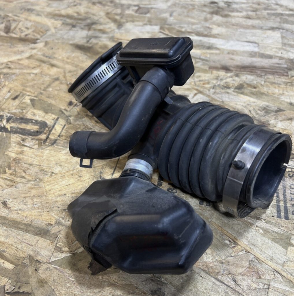
Automakers use resonators and quarter wave tubes to cancel out problem tones from your intake just like for your exhaust, they are just made of black plastic instead of metal. The accordion style intake tube has its own bands of frequencies that it reduces (and some that it increases). Interestingly, when the valves are closed, intake and exhaust runners act as resonators since they are basically closed ended tubes.
Let’s Get Loaded
Another major factor that affects your engine’s sound is load, or how hard your engine is working. When you are cruising down the street and sink the gas pedal to the floor the engine will not only get louder, but the character will change. You all know how addictive this can be, doing short pulls to hear your motor growl. This is due to a combination of all the factors described above.
When you stomp on the gas a few things happen. You are signaling to the engine that you want to go faster. To go faster, the engine needs to work harder and produce more power. Your throttle butterfly opens fully; that metal door is no longer blocking all that intake noise so those frequencies we described above are more prominent. The engine is now sucking in much more air increasing any flow noise in the intake system. You can hear this really well in the video below where I took my old NSX to a track day. (Amazingly the current owner of that very NSX used it as an intake noise benchmark for the Corvette!)
The ECU tells the injectors to spray more fuel. The resulting explosions in the cylinder now create significantly more pressure. The increased pressure pushes down on the piston with alacrity, generating the torque that pushes you back in your seat. It also causes the pressure waves we described above to have a lot more … pressure. The amplitude, or distance between the peak and trough of the sound waves is larger. This means that distinctive chord of frequencies singing out of your tailpipe is much louder.
We take this into account when we build NVH simulator models for cars. We tap the throttle pedal wires with a simple volt meter so we can measure what the throttle is commanding the ECU. We then go on the track and measure the sound and vibration of RPM run-ups in different gears, increasing our throttle by 10% each run until we hit 100% or full throttle. It takes a precise foot and a lot of recordings to get all this data. In the end we have this matrix that can be plugged into the simulator program that will give us accurate sound no matter what RPM, gear, or throttle position the driver is commanding.
Got Boost?
Finally we get to forced induction, as we can’t have an engine noise article without mentioning our beloved turbochargers and superchargers. I assume you understand the basics of how these systems work. They compress the air in the intake system, squeezing more air into the cylinders which allows for more fuel which increases horsepower. Superchargers and turbochargers operate differently and each has a distinctive sound.
The compressor on a supercharger is belt driven. In a roots style supercharger, this belt spins a pulley which turns a set of gears connected to twin rotors. These rotors turn in opposite directions, forcing air into the engine’s intake. The supercharger whine you are familiar with comes from these gears meshing together. Remember the order explainer at the beginning of the article? The frequency is related to the number of gear teeth and the RPM they are spinning.
These are typically straight cut gears, which are louder than other types. Since the supercharger is spun directly by the engine, the RPM of the gears is always proportional to the engine RPM as they are connected by a belt. This means the frequency of your supercharger whine always increases and decreases linearly with the engine RPM. In the Bonneville sound plots, you can see this high frequency whine rising in line with the engine orders.
Turbochargers operate much differently. There is no direct connection between the spinning of the engine and the turbine. Instead, the gas flowing out of the exhaust spins one end of a turbine wheel, while the compressor wheel on the other end compresses the air in the intake tract. The whistle you hear is a combination of many things: the turbine blades passing through the air, the bearings, and the flow of air through the turbine and compressor housings.
Turbos spin at significantly higher RPMs compared to superchargers, in the hundreds of thousands of RPMs vs tens of thousands. This means a turbo’s whistle is much higher in frequency than a superchargers whine. The turbo’s RPM increases with exhaust pressure (causing the rotor to spin faster) so the frequency increase is more throttle dependent, instead of RPM dependent like a supercharger. This also causes the whistle’s frequency to increase exponentially vs linearly for supercharger whine.
There are significant plumbing changes for your intake and exhaust when adding forced induction. As we discussed earlier, a turbocharged engine will need a special exhaust manifold design to route those gasses through the turbine, affecting the chord your engine makes. You also get all the flow noise through the intake pipes and the addicting flutter from your blow off valve as it vents pressure when you let off throttle.
The rotors of a supercharger are in the direct path of the intake frequencies coming out of the engine. For a turbo this is true on the intake and exhaust side. This muffles that chord of frequencies we talked about, and is why some people prefer the sound of naturally aspirated engines. However the signature whistle or whine, the flow noise, and all the extra power makes it worth it.
Motoring Music
So your intake and exhaust are like two variations on the same base chord, each with its own harmonics and timbre, coming together to make a symphony of sound. Or silence if you drive a luxury car. There is a ton of more stuff I’d like to go into, but this covers all the basics. What I hope you take away from this article (besides a headache) is that a vehicle’s sound isn’t just a random confluence of physical phenomena that we can barely hope to understand. It’s like the instantly recognizable sound of a musical instrument, whose signature can tap into a deep well of emotions and memories. Their resulting sound is a combination of physics, human ingenuity, trial and error, availability of materials, and the evolution of science, manufacturing, and engineering technique over the lifetime of its development. The memories of our experiences dissolve like herby croutons into the steamy soup of cool sounding things I said in the last sentence, giving it texture and flavor.
You get chills from the high pitched wail of an F1 car, but why? To make maximum power, racing teams typically used engines with more cylinders like V8s, V10s and V12s. These created “base chords” of tones that were higher in frequency and more widely spaced than the pedestrian four and six cylinder engines we putter around in every day. Short, equal length exhausts and unfiltered individual throttle bodies make the most amount of power and allows that chord to sing freely and cleanly into the open air, not getting choked by mufflers, filters, and pipes. Cutting edge technology, exotic materials, and fanatic precision and attention to detail in the pursuit of horsepower allowed these engines to rev to stratospheric heights incredibly fast, hitting notes our vehicles could never dream of. Feeling the sound in your chest as these alien cars blast by flat out at mind-blowing speeds, over 700 horsepower at 16,000+ RPM, this marvel engine ripping, hurtling this ultra-light, strong yet delicate wisp of a car through space as fast and as long as the driver dares keep his foot pinned to the floor before the lizard part of his brain starts screaming about self preservation.
You see these awesome feats of humans moving around at hitherto unimaginable speeds, the thrill and heroism of competition, and all the work it takes to get there. You imagine what the driver is experiencing and are awestruck, just feeling struck by all the awe from so much awesomeness. Or you feel the deep rumble and burly roar of a V8 muscle-car as it shoves you into your seat with a wall of tire shredding torque. These experiences become a part of you, and are summoned from the depths when a particular bundle of frequencies graces your eardrums.
On the other hand, we can quiet down all these constant, physically loud, explodey events using our know-how. You can have a pleasant conversation with other people in your cabin without raising your voice while fuel and air explodes thousands of times a minute a handful of feet away. All these variables, dimensions, and physical properties are modeled in computers, tested on the bench or dyno, then tested more in the vehicle by hoards of engineers and technicians. The end goal is to make a powertrain whose sound exceeds your expectations, whether it’s for quietness and refinement, or egging you on to bury the throttle one more time.


I missed this article the first time. This is amazing and needs to be resurrected to the main page. It’s too good to only be up once and then gone.
Wow. This NVH stuff involves an astonishingly wide spectrum of applied physics. From the body panels and components inside and out to the mechanicals of the engine and beyond and even the fluid dynamics of intake, exhaust and the whole vehicle passing through the atmosphere. I had never thought this deeply about it, but it was fascinating to read and learn.
Your writing is very clear, and it was nice that you wrote in a way that you weren’t assuming we all already had our PhDs. The tap hammer article was very interesting too!
You would be a great professor or, perhaps less hassle, a special guest lecturer.
Thanks! I really appreciate it. Its one of the things I really enjoy about NVH. It encompasses a wide range of phenomena, and the work has a good mix of theoretical analysis and getting your hands dirty on physical parts/cars.
Wow, I’m blown away by how much work and detail went into this. Amazing
Thanks! Glad you liked it!
This is wicked awesome, thanks for writing up and sharing! Probably could have been a series of articles…but the principles carry all through and I love the level of detail. So how does Yamaha always make such amazing sounding engines? Particularly intake noise, they just spend more time tuning all these factors more effectively? I’m much more of a sucker for good intake noise over exhaust noise (I can enjoy awesome noises without driving myself crazy on the highway or waking up the neighborhood and making myself a cop magnet, haha).
It took me a while to get through this thorough article, but it was worth it! Excellent job Steve!
I had to cut up this article into three nights but I’m so glad I stuck with it. What an incredibly informative, interesting, intelligent piece.
Thank you! I appreciate the comment
just brilliant Steve, thank you!
i felt like i just got a phd but have been enjoying this mountain dew the whole time instead
Wow. That was a lot but I’m glad I read it.
I deleted the front resonator on my turbo S5 which made it sound better, but it doesn’t drone on the highway. I also deleted the intake resonator from the supercharged Q7 so I can hear that sweet whine. The internet told me these two things would make the cars sound better, and the internet was right, but now I understand why.
Glad you enjoyed it!
Wow, I feel like I just audited an automotive engineering class! That took a long time to read and listen to the sounds but it was totally worth it for any gearhead. Thank you for sharing.
As an example of how this could be real-world useful to an enthusiast, I spent many hours trying to build a compact dual exhaust for my Corvair flat 6 that would sound good but not crazy loud or droning. I now understand why some of the choices I made along the way were poor and why the final result I stumbled upon sounds good.
Thanks! Even with all the engineering know how there is a lot of trial and error in NVH.
Thank you for this article Steve, it’s incredibly well written and must have taken you ages to make it understandable to us Autopian Simpletons! I feel like I’ve learned a lot reading it and as per the comment from @Regorlas I never realised that the distinctive noises of various engines was all in the sucking and blowing(!) rather than the exploding that is happening under the bonnet/hood.
Thanks! I agree it is a little counterintuitive, you’d think the explosions would be the loudest part.